Ai-Thinker A9 module with custom firmware
Let's discover the A9 GSM module and the possibility to flash it with a custom firmware!
After using the Ai-Thinker A6, I found the Ai-Thinker A9, which can be controlled with AT commands, but also programmed thanks to an Ai-Thinker SDK. Let's try that!
Ai-Thinker published an official SDK documentation, as such as an SDK on Github.
SDK overview
This board seems quite promising, as the SDK contains a lot of features, from the basic one (SMS, call, SPI, I2C...) to some which are more complex (MQTT, FileSystem on SD card, FOTA...).
For each API, you will find one example shipped with the SDK ready to be compiled and uploaded to the development board.
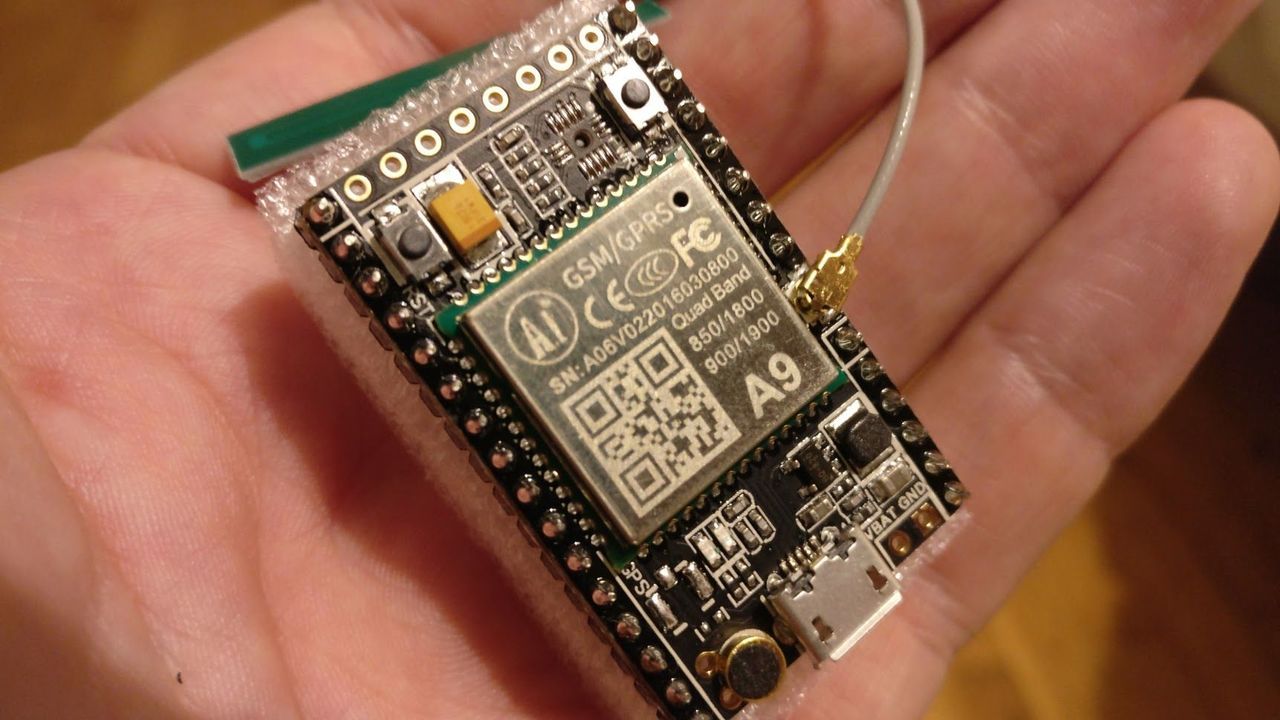
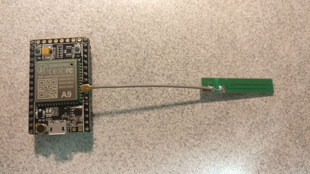
Development board
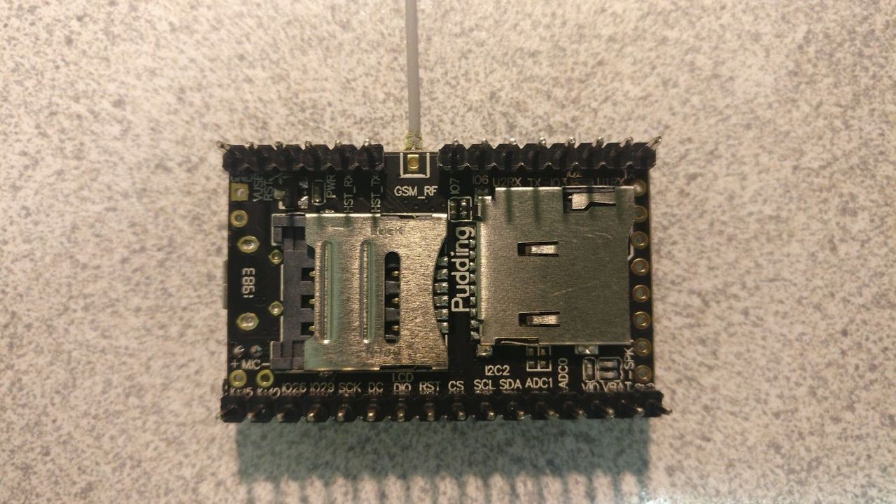
Ai-Thinker developed a small board which is perfect for hobbyists like myself! It's called "Pudding" board.
This boards has everything that we need, and even a SD card reader and embedded mic!
Development environment setup under Windows
- Download CSDTK4.2 (baidu cloud, MEGA cloud, direct link)
- Get SDK from Github (pre-release V2.112)
- Decompress the downloaded CSDTK file (e.g:
C:\CSDTK) - Run
config_env_admin.batfile in CSDTK to set environment variables - Decompress the CSDK downloaded file (e.g:
C:\GPRS_C_SDK) - Open a PowerShell terminal into the CSDK folder and type
.\build.bat appto build theappfolder source code in debug mode
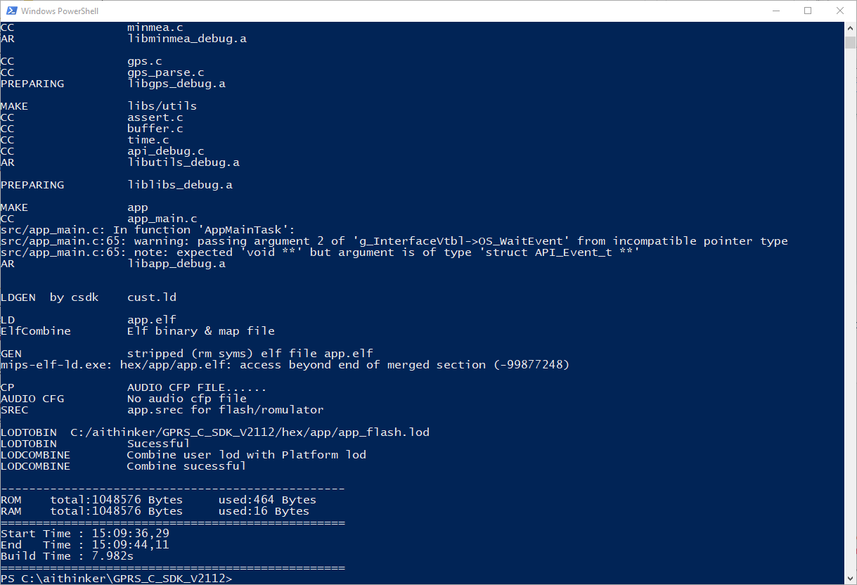
Build command
You can use ./build.bat script to build project:
./build.bat $PROJ: compile app module,e.g.:./build.batsh appto compile the source code ofappfolder./build.bat demo $PROJ: compile a demo project, e.g.:./build.bat demo gpioto compilegpiodemo./build.bat clean $PROJ: clear the build files of$PROJ./build.bat clean all: clear all the build files./build.bat demo $PROJ release: build a release version, e.g.:./build.bat demo gpio release.
By default, build.bat will build a debug version.
In release mode, the watchdog resets the system after an error.
A build and an hex folder will be generated after compile.
Two hex file will be generated into the hex folder (*_B*.lod and *_flash.lod). The bigger file should be flashed after each SDK upgrade. The smaller one will contain the compiled source code and must be uploaded after compilation.
Upload source code
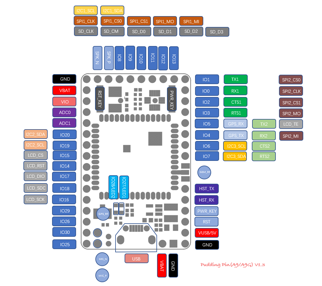
Hardware connection
As the A6 chip, the download interface is the HST interface. The pins HST_RX and HST_TX are respectively connected to the TX and RX pins of the USB to serial module.
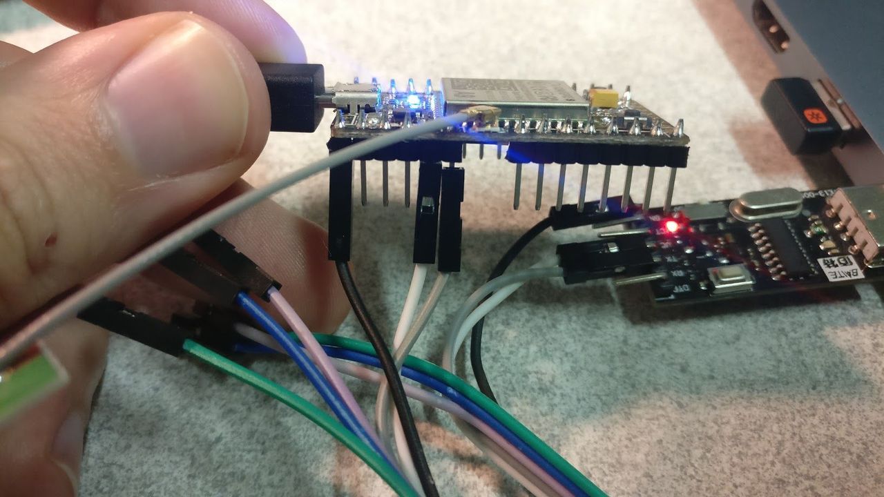
To power the device, you can use a lithium battery (voltage 3.8v ~ 4.2v) (VBAT pins), or use a 5v power supply (5v input pin or USB input).
Please note that when using lithium battery power supply, the POWER KEY must be pressed for about 3 seconds to power on the module (not the case with the USB plug).
Software tool
In CSDTK folder, start cooltools\coolwatcher.exe.
Select profile 8955 and change the lastcomport value by the COM port number of your USB/Serial converter, then click on the "OK" button
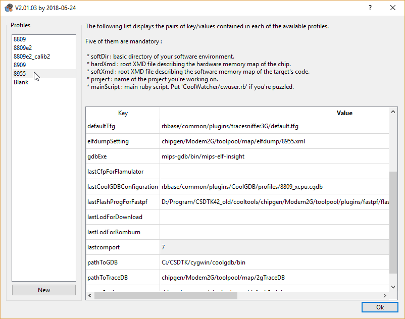
You should be connected :
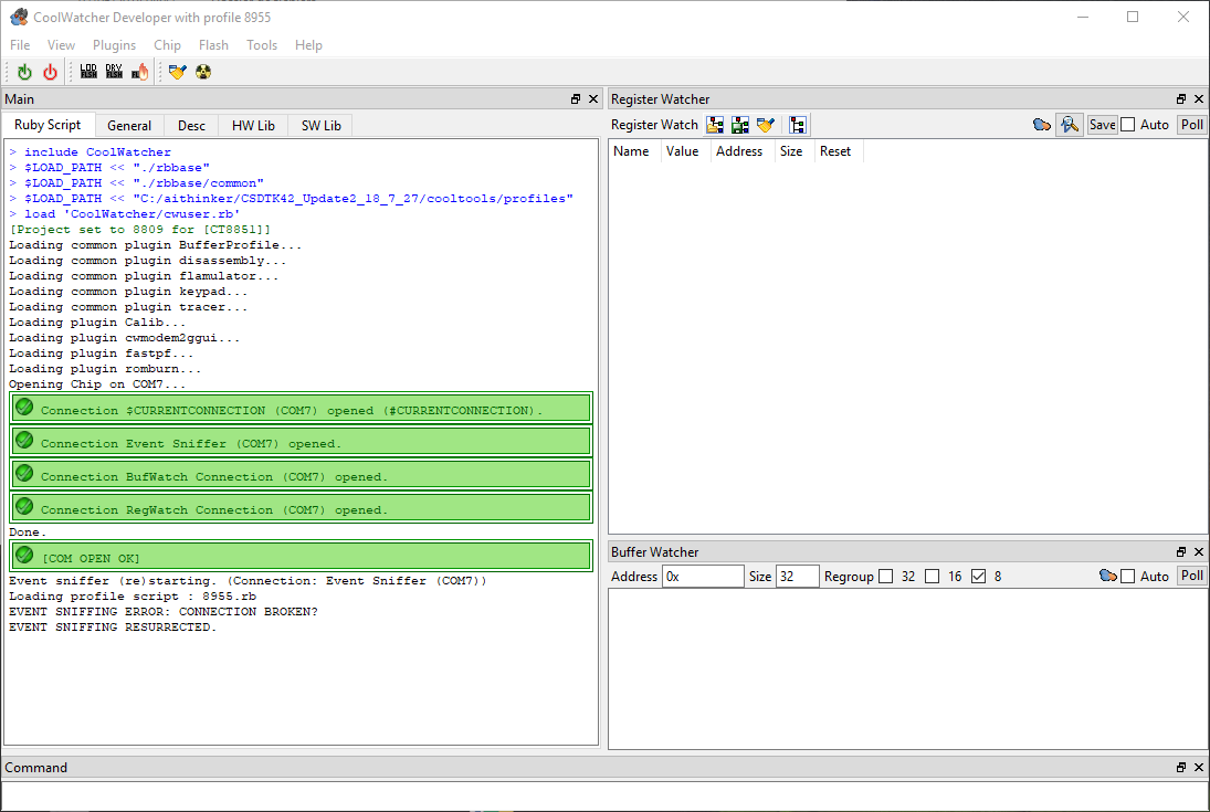
Select the flash programmer with the "Flash > Choose Flash Programmer..." menu.
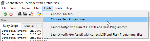
In the cooltools\chipgen\Modem2G\toolpool\plugins\fastpf\flash_programmers folder, select the *_8955_*_spi32m_ramrun.lod file (e.g: host_8955_flsh_spi32m_ramrun.lod).
You can now burn the firmware. Click on the "LOD" icon:
In the CSDK hex folder, you should find a *_debug.lod file and a *_flash_debug.lod file. The *_debug.lod file should be burn first, and need only to be flashed when the SDK is updated.
To flash a file once selected, click on the burn icon:
You can try it as I did with the GPIO example.
After a code change, you just have to compile the source code and press the burn button again. You don't need to re-select the file.
Debug
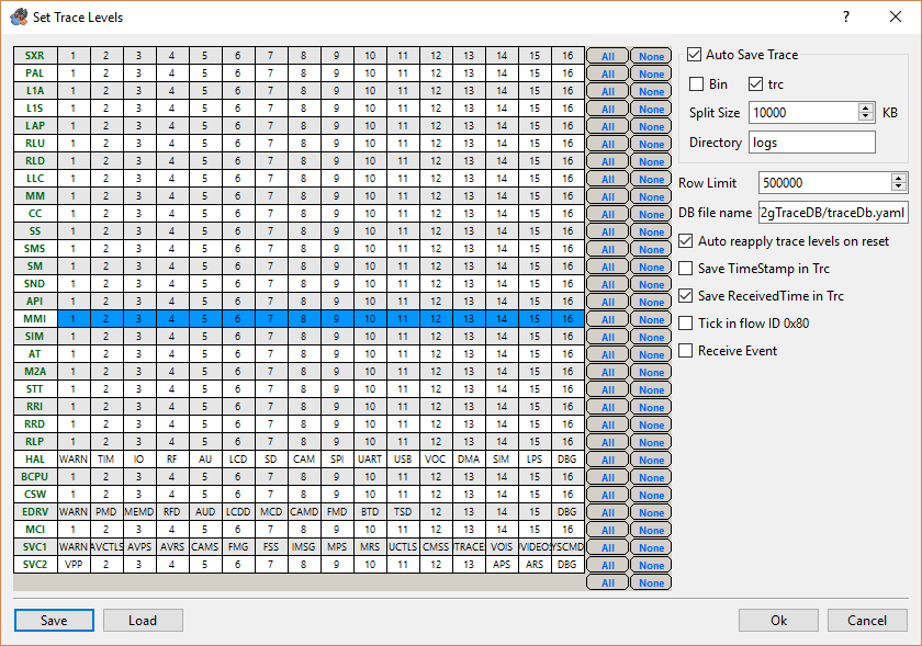
Click on Plugins -> Active Tracer. On the Trace tool window, click on Set trace levels icon:
And change the settings according to the following screenshot:
You can now click on the Start sniffing traces button.
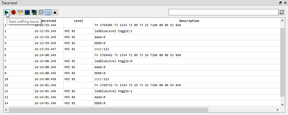
Each time that the Trace() function (api_debug.h) is called in the source code, the trace tool will display the content.
Conclusion
Now that I have seen this board, I want to use it on a project!
The main difficulty will be to drive other modules as the GPIO levels (1.9V or 2.8V) are quite different from hobbyist modules (3.3V / 5V).