Arduino pro mini @ 1MHz - 1.8V
I'm always trying to find the best option for low power consumption projects. Using the Arduino pro mini at 1MHz and 1.8V gives new perspectives!

During my water tank project, I realized that even with 3 AAA batteries, the voltage will go below 3.3V quite quickly :
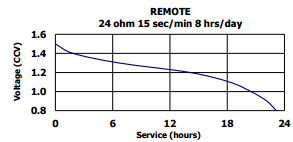
Extract from AAA Energizer datasheet
If I extrapolate, it will remain around 25% of capacity of each battery when the voltage will be at 3.3V (1.1V per battery).
The cut-off voltage of these batteries is 0.8V. With 3 batteries, I will get 2.4V.
The ATmega328P will still work under this voltage, but only at 8MHz (which is the frequency of the Arduino Pro Mini 3.3V).
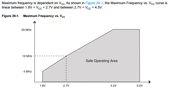
But why stop here ? With 2 batteries, it will go lower than 1.8V.
For that, we need to have a maximum frequency of 4MHz.
From what I understand, we have two options :
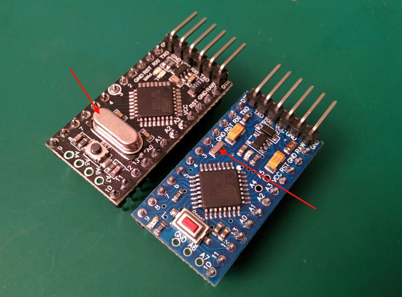
- Change the crystal oscillator of the Arduino
- Use the internal oscillator of the ATmega chip, and go down to 1MHz
Today, I will try the second option. I think that it is possible to change the crystal of some Arduino Pro Mini (it has to be visible), but I don't have the pieces for the moment.
Internal RC oscillator
Atmega datasheet: By default, the Internal RC Oscillator provides an approximate 8MHz clock. Though voltage and temperature dependent, this clock can be very accurately calibrated by the user.
I don't have the equipment to calibrate the oscillator. But as I don't make a time sensitive device, I don't think it will ba a problem. The factory calibration accuracy is +/-10% (as the user calibration accuracy is +/-1%).
The oscillator input can be selected through the fuses of the ATmega.
The fuses can be program to configure the chip. Contrary to what the name suggests, the fuses configuration is reversible. However, some of them are used to enable/disable some functionalities used to flash the ATmega (external reset, serial programming...) so be careful to check your modifications before applying them.
Flashing process
If you don't already know, the classical way to use the Arduino, is to have a bootloader (small program), started at the reset of the atmega.
The bootloader enable us to change the active sketch through the serial port (write into memory), read memory, get device signature, and so on. It also starts the uploaded sketch when programming mode is not started through the serial port.
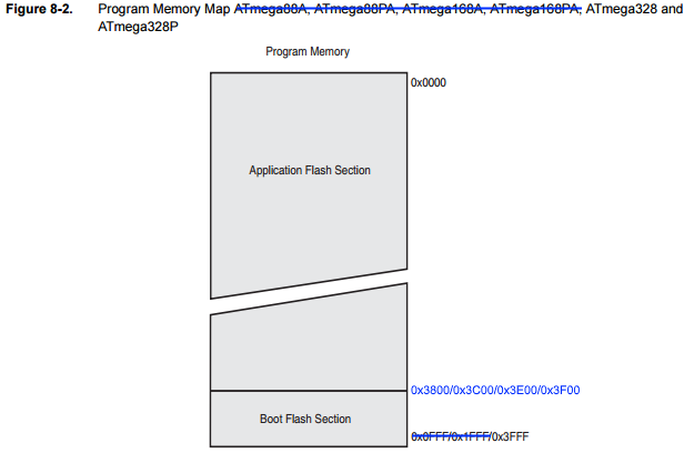
On the ATmega328p, the bootloader can have 4 different sizes (256 bytes, 512 bytes, 1024 bytes or 2048 bytes).
With the ATmega328p, two bootloaders are commonly used:
- ATmegaBOOT (2kB), original Arduino bootloader [GitHub];
- Optiboot (500 bytes), lighter bootloader, default with Arduino Uno [GitHub].
You will find other bootloaders for Arduino Mega (ATmega1280) for example.
The second way to use the ATmega, is to program it with an ISP programmer, which doesn't need the bootloader. As such, the bootloader can be removed, allowing a memory gain up to 2kB (depends on the bootloader).
As we want to change the frequency of the ATMega328p, we have two options :
- Bypass the bootloader, programming the atmega directly with the ISP programmer;
- Flash a compatible bootloader on the Arduino with the ISP programmer.
Whatever option is used, an ISP programmer is required.
Moreover, if you want to use a bootloader, you need to compile it (or find it somewhere on the internet), as the Arduino IDE does not come with a compliant bootloader.
For now, I will bypass the bootloader as I don't want to install the toolchain required to build it.
Changing the fuses
To change the fuses, you cannot use the serial / USB link. You will need an ISP programmer. Same remark with the Arduino Uno and the Arduino Nano.
Note: if we used the bootloader method with the Arduino IDE, the fuses will be automatically changed during the bootloader flashing process (always through the ISP programmer).
The ATmega328p has 3 fuses (+2 special fuses, not mentionned here), 1 byte each :
- Extended Fuse
- High Fuse
- Low Fuse
Please note:
- A bit set to "1" is "unprogrammed", and a bit set to "0" is "programmed";
- Some numerical values refer to fuses containing undefined bits. Depending on the target device these fuse bits will be read either as "0" or "1". Everything is fine if the values read from the device are either the same as programmed (for AVRdude software, use "1", for Arduino IDE, use "0" for undefined bits with atmega328p).
- The "default value" column of the datasheet is for standalone chips. For the Arduino chip, the fuses configuration is different.
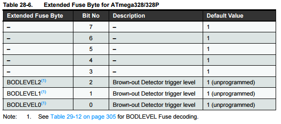
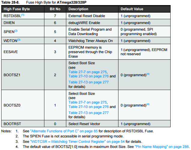
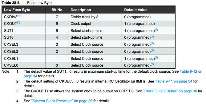
Datasheet extract
Following paragraphs are extracted from the Atmel datasheet.
Extended Fuse
High Fuse
Low Fuse
Configuration to apply
I played with the fuses values with the following tool : http://www.engbedded.com/fusecalc
By default, on the Arduino Pro Mini, the fuses have the following values:
- Low fuse: 0xFF
- High fuse: 0xDA
- Extended fuse: 0xFF / 0x05
We are tying to:
- Enable the internal oscillator (8Mhz +/- 10%); [CKSEL=0010]
- Keep the startup time at 65ms (to allow the oscillator to stabilize); [SUT=10]
- Divide clock by 8 internally; [CKDIV8=0]
- Set the brown-out detection level at Vcc = 1.8V; [BODLEVEL=110] (could be disabled for save more energy with [BODLEVEL=111])
- Disable the boot reset vector as we don't use a bootloader [BOOTRST=1].
Which gives us:
- Low fuse: 0x62
- High fuse: 0xDB
- Extended fuse: 0xFE / 0x06 (or 0xFF / 0x05 for disabling the brown-out detection)
Material
- USBTinyISP V2 (cheap ISP programmer)
- Arduino pro mini 3.3V @ 8MHz
- External power supply @ 3.3V
- Breadboard, cables...
You can use other ISP programmers and even use an Arduino as an ISP programmer, but the following commands will be dedicated to the USBTinyISP.
USBTinyISP V2
Warning
There's a jumper sticking out near the cables, nammed JP3. When the jumper is in place (connecting the two wires) then that means that the USBtinyISP is providing 5V power to the device being programmed.
So, has the Arduino Pro Mini needs to run at 3.3V, I removed the jumper![1]
More infos on Adafruit
Softwares
- AVRDude (download link)[2], which allows to change the fuses through the ISP programmer
- Arduino IDE[3], which allows to flash and build a sketch through the ISP programmer
Schematics
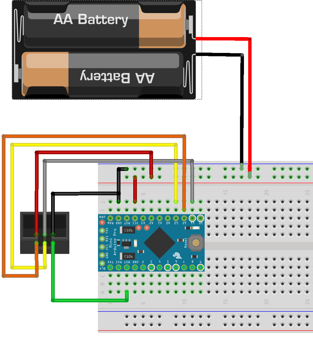
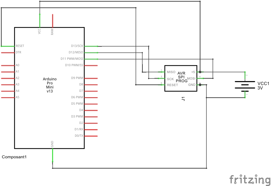
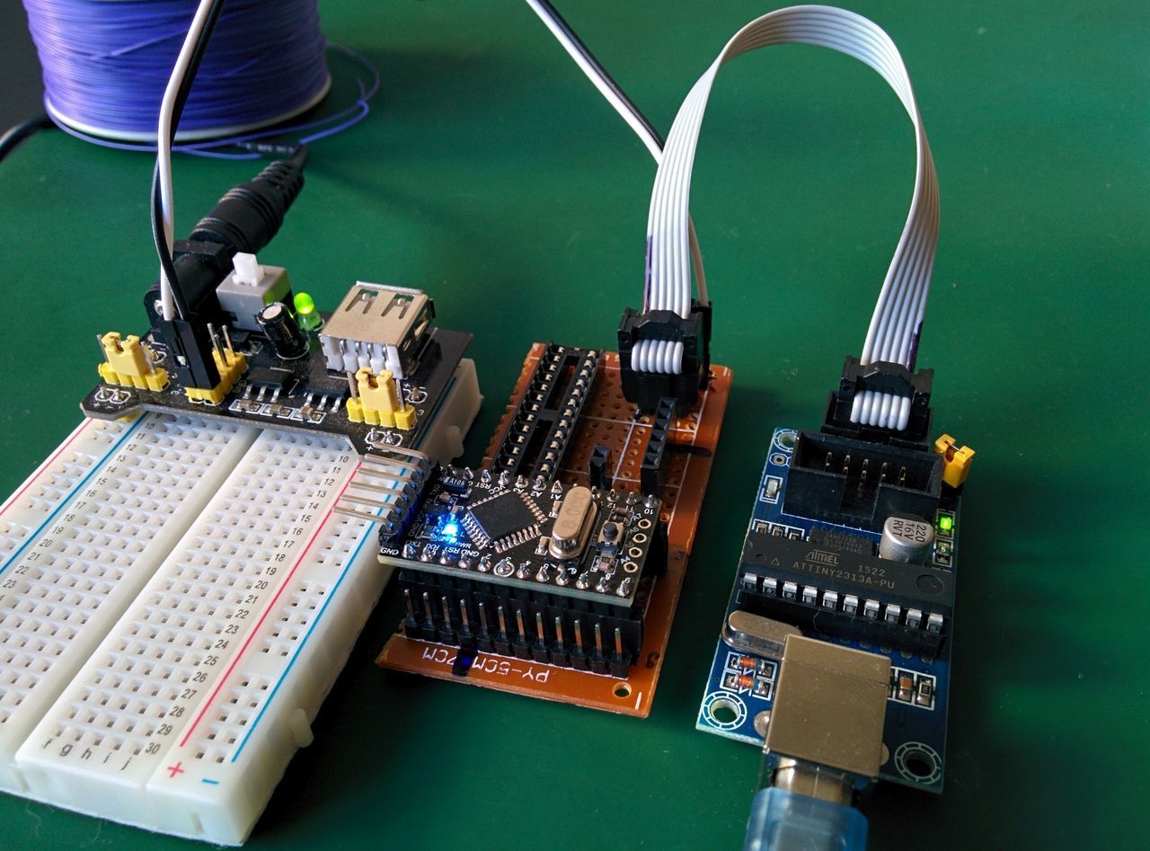
Picture
I made a little circuit to be able to program the Arduino pro mini with the USBTinyISP (or the serial interface for latter, if I manage to build a custom bootloader).
I also added a slot for a ATMega328p chip (for another project).
Using AVRDude
I added the path of the AVRDude executable file in my Path.
To check the connection and get the current fuse values, run the following command:
avrdude -c usbtiny -p atmega328p
To "burn" the fuses, use the following command:
avrdude -c usbtiny -p atmega328p -U lfuse:w:<0xLL>:m -U hfuse:w:<0xHH>:m -U efuse:w:<0xEE>:m
With :
- <0xLL>: Low fuses value in hexadecimal
- <0xHH>: High fuses value in hexadecimal
- <0xEE>: Extended fuses value in hexadecimal
Upload a sketch through the ISP link
Now that the Arduino Pro Mini is at 1Mhz, it's time to upload a sketch :)
To do that, I added a board, compatible with the bootloader, at the end of the "boards.txt" file of the Arduino IDE.
C:\Users\[user]\AppData\Local\Arduino15\packages\arduino\hardware\avr\[X.Y.Z]\boards.txt
promini1MhzInt.name=Arduino Pro Mini (1MHz internal, 1.8V)
promini1MhzInt.upload.tool=avrdude
promini1MhzInt.build.board=AVR_PRO
promini1MhzInt.build.mcu=atmega328p
promini1MhzInt.build.f_cpu=1000000L
promini1MhzInt.build.core=arduino
promini1MhzInt.build.variant=eightanaloginputs
After restarting the IDE, the new board is present.
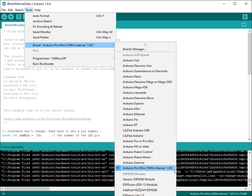
I selected the programmer with "Tools -> Programmer".
Now, I can select the new board and upload a sketch through the ISP interface (not serial) !
This will erase the bootloader and upload the sketch through the USBTinyISP.
That's it ! Time to play with this low power device :)
To restore the board with a bootloader @ 8MHz
If you want to restore your card to use the external oscillator @ 8Mhz, just select the board "Arduino Pro or Pro Mini", then the processor "ATmega328 (3.3V, 8 Mhz)", and restore/burn the bootloader though "Tools -> Burn bootloader"