ATtiny85 development boards
There is a lot of ATtiny dev boards out there. Let's compare them quickly.

I recently acquired 3 different ATtiny development boards with USB ports.
It should be possible to upload Arduino sketches through the USB port.
They are working at 5V @ 16Mhz.
To do so, a bootloader has to be flashed on those development boards.
Let's flash the bootloader !
The common bootloader for those tiny boards is MicroNucleus.
To flash the board, I will use a USBTinyISP, but you can also use an Arduino loaded with the ArduinoISP sketch (you can find examples online).
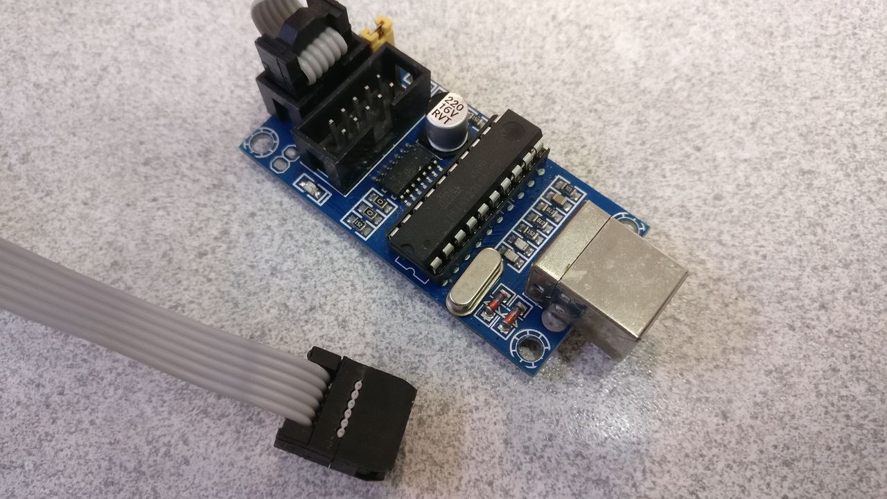
As a reminded, the USBTinyISP pinout :
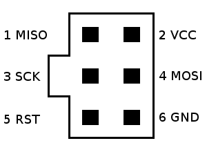
I personnally use an USBTinyISP:
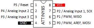
And the mapping between Px and real pins :
I downloaded the V1.1 release of the firmware source code. Inside the ZIP file, under "firmware/releases", you will find the HEX files of the releases.
To flash the HEX file, I used AVRDude in the "releases" folder:
avrdude -c usbtiny -p t85 -U flash:w:filename.hex -U lfuse:w:0xe1:m -U hfuse:w:0xdf:m -U efuse:w:0xfe:m
You can also use the RESET pin as an DIO, by setting the hfuse to 0x5f. If you do so, you will not be able to flash the device with ISP anymore !
You can now disconnect the ISP probe from the board.
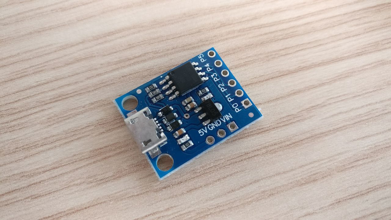
Model A
Nucleus file used: micronucleus-1.11-ledpb1.hex
The header is compatible with the ISP pinout, but you will have to bend two pins.
The built-in led is mapped on P1 (pin 6).
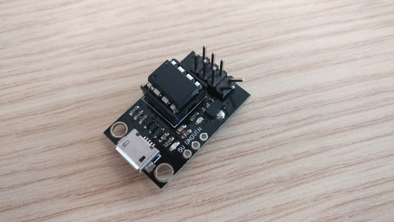
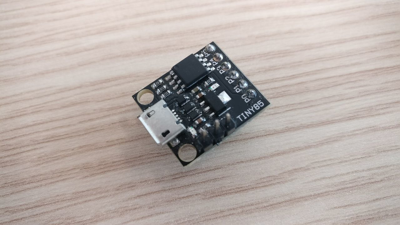
Model B
By default, P5 cannot be used at the reset pin, so it's not possible to flash a new bootloader with ISP.
My device has firmware version 1.6.
The built-in led is mapped on P1 (pin 6).
Model C
By default, P5 cannot be used at the reset pin, so it's not possible to flash a new bootloader with ISP.
My device has firmware version 1.6.
The built-in led is mapped on P1 (pin 6).
Restore the RESET pin
On model B and C, as the RSTDISBL fuse is set, you cannot use ISP to flash a new bootloader.
To restore the reset fuse, you can create a HV Serial programmer with an Arduino.
I will try that another day.
Time to use Arduino IDE
Tu use you board in Arduino IDE, you have to add Digispark boards ("File" -> "Preferences" -> "Additional Boards Manager URLs"):
http://digistump.com/package_digistump_index.json
Now, install the boards ("Tools" -> "Board", and select "Boards Manager") named "Digistump AVR Boards" with the "Install" button.
Under Windows, a "Driver Install Wizard" window will pop up to install the dedicated drivers.
You can now select the board named "Digispark (Default - 16.5mhz)".
Create a new sketch to blink the built-in led :
#define LED_BUILTIN 1

// the setup function runs once when you press reset or power the board
void setup() {
  // initialize digital pin LED_BUILTIN as an output.
  pinMode(LED_BUILTIN, OUTPUT);
}

// the loop function runs over and over again forever
void loop() {
  digitalWrite(LED_BUILTIN, HIGH);   // turn the LED on (HIGH is the voltage level)
  delay(1000);                       // wait for a second
  digitalWrite(LED_BUILTIN, LOW);    // turn the LED off by making the voltage LOW
  delay(1000);                       // wait for a second
}
Disconnect the board from the computer, click on the "Upload" button before plugin the board again.
The code upload should begin, then end with the message "Micronucleus done. Thank you!".
The built-in led should now blink !