Audio player [1]: Concept and first circuit
A real IoT device, WiFi enabled, connected to a MQTT server which can play sound on demand!
![Audio player [1]: Concept and first circuit](https://storage.ghost.io/c/fe/14/fe1439bb-44cb-4fc0-aa30-44bf49d2ab9f/content/images/size/w2000/2017/08/IMG_20160511_082710-1-.jpg)
Today, I want to build a simple audio player.
The concept is simple. Imagine that my flat will be full of IoT devices. When something important happen (e.g. someone breaking my cellar), and that I am at home, I would like to have a sound played to notify me.
First attempt goal
As I don't have (yet !) a lot of IoT devices at home, I want to build a prototype for another purpose: inform my brother when a Doctor Who episode is on air !
I hope that this device will be finished for Chrismas, before the "special" episode.

This device will play the "VWOOORP" of the Tardis when an episode begins in UK, and maybe I will add a blue LED with dimming the day of the episode.
If I have the time / budget, I will make a plastic / wood case reminding the serie.
Requirements
Let's try to define the device to build:
- Low cost (always !)
- Always listening to an event
- Used at home only
- Stand alone
Solutions
With those specifications, I can deduce:
- Main power supply: plugged on wall
- Connectivity: Wifi (always available)
Big picture
Of course, this device has to be a part of my IoT big picture. The device will be connected to an MQTT broker, waiting for some order to play a sound.
The logic of when / why / which sound to play will be left to the cloud software (sometimes named "the controller").
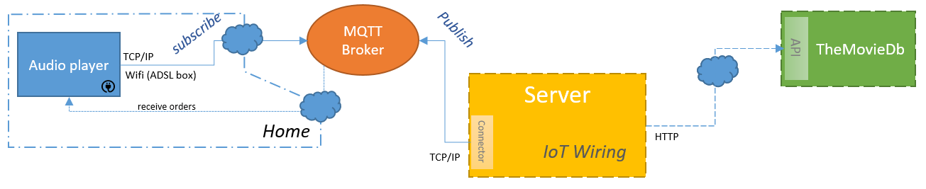
So, in our particular case of the Doctor Who serie reminder, the device should receive some orders (play "Doctor Who" sound, start / stop the LED pulse), and send its state.
And in bonus, it could be interesting to add OTA updates as I will not have access to the device once given to my brother.
Messaging
As I said before, I want to use the MQTT broker to [send order to] / [receive state from] the ESP8266.
For testing purposes, I used the test mosquitto server.
Orders
- Play track n°X
- Stop
- Pause
- Mute
- Unmute
- Start LED pulse
- Stop the LED
State
- Playing / Stopped / Paused
- Track number
- Volume level
- LED (on / off)
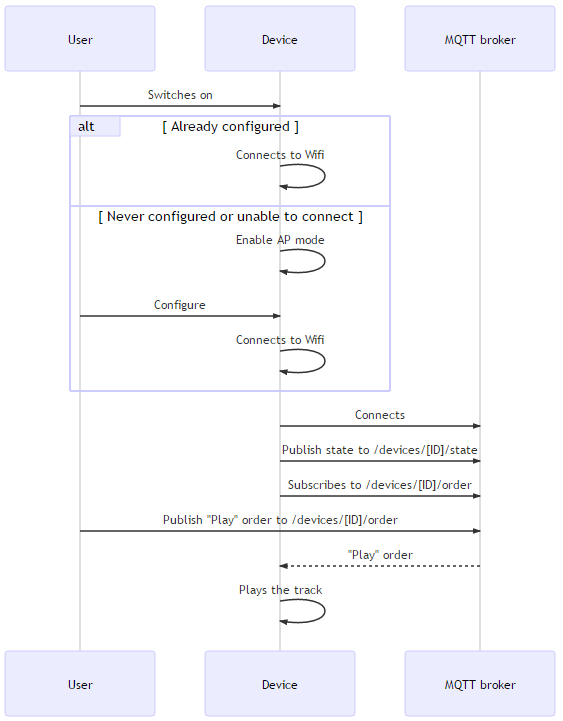
Sequence diagram
This diagram is a first draft.
I think it misses :
- Some "state" messages at each action
- The lwt message
- A heartbeat message (but maybe the MQTT lwt message is enough)
- The retain / non retain value of each message.
The ID of the device will be a unique chip identifier.
Material
Reminder: This device has to be cheap !
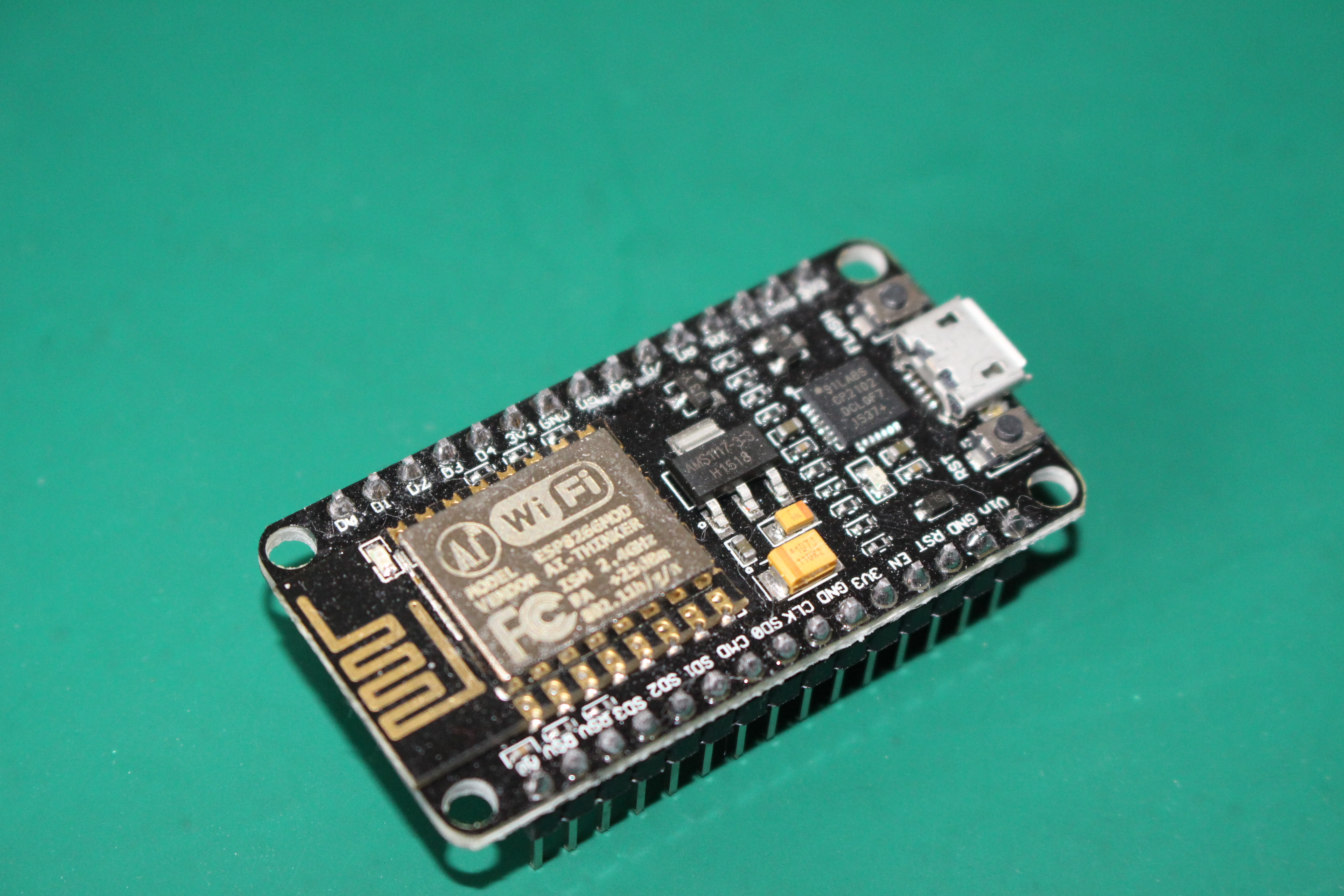
Base board
As I want Wifi connectivity, the ESP8266 seems to be the right choice.
I have 3 modules in my possession: ESP-01 (this pins, few I/O), ESP-07 (with big antenna) and ESP-12 (antenna on PCB).
I will use the ESP-12 to have lots of I/O, and compact PCB.
For the development, I will use the NodeMCU dev board.
Music
I found the WTV020M01 module (V1.0 / 20120112), which can play sounds directly from a micro-SD card.
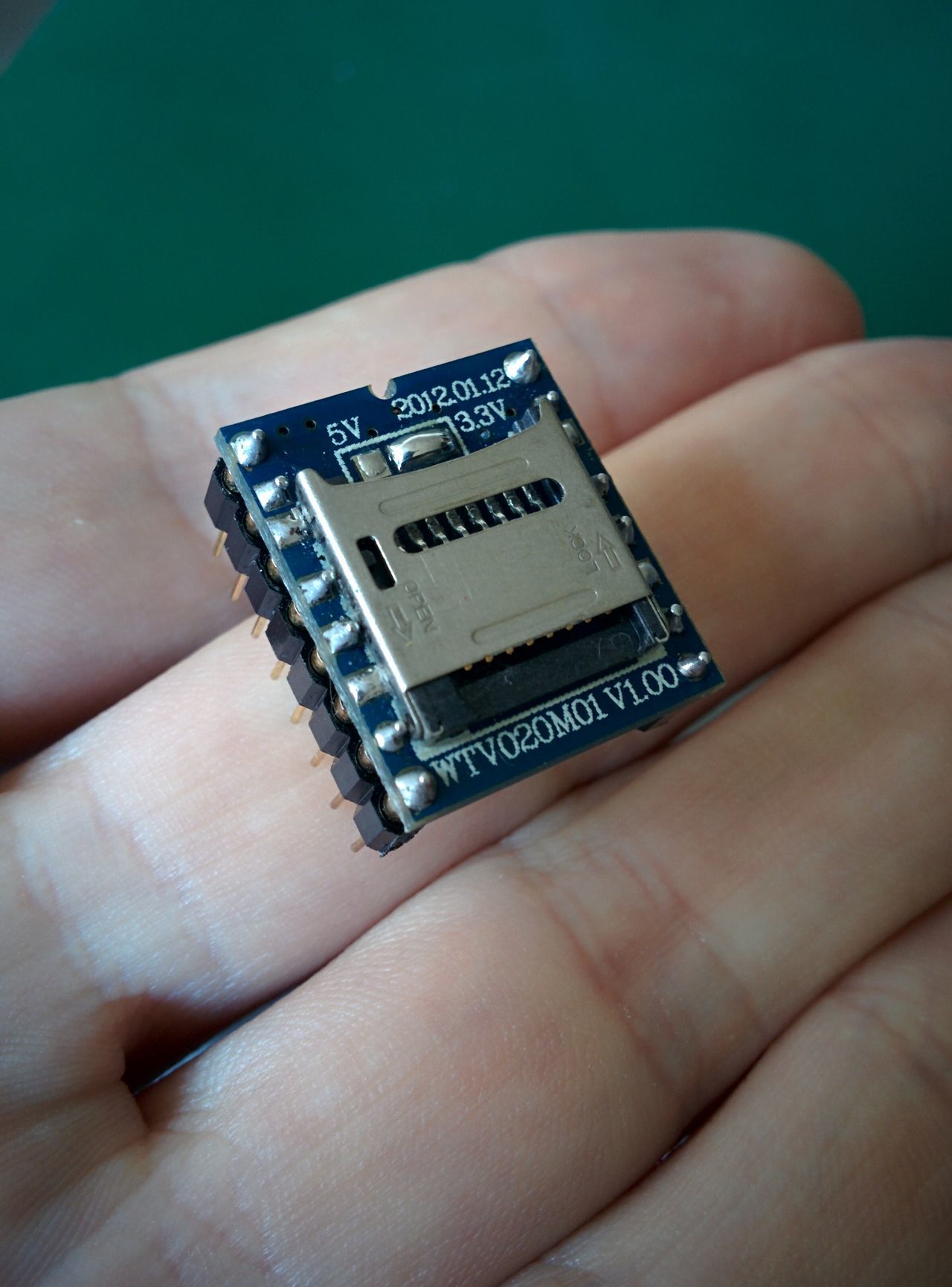
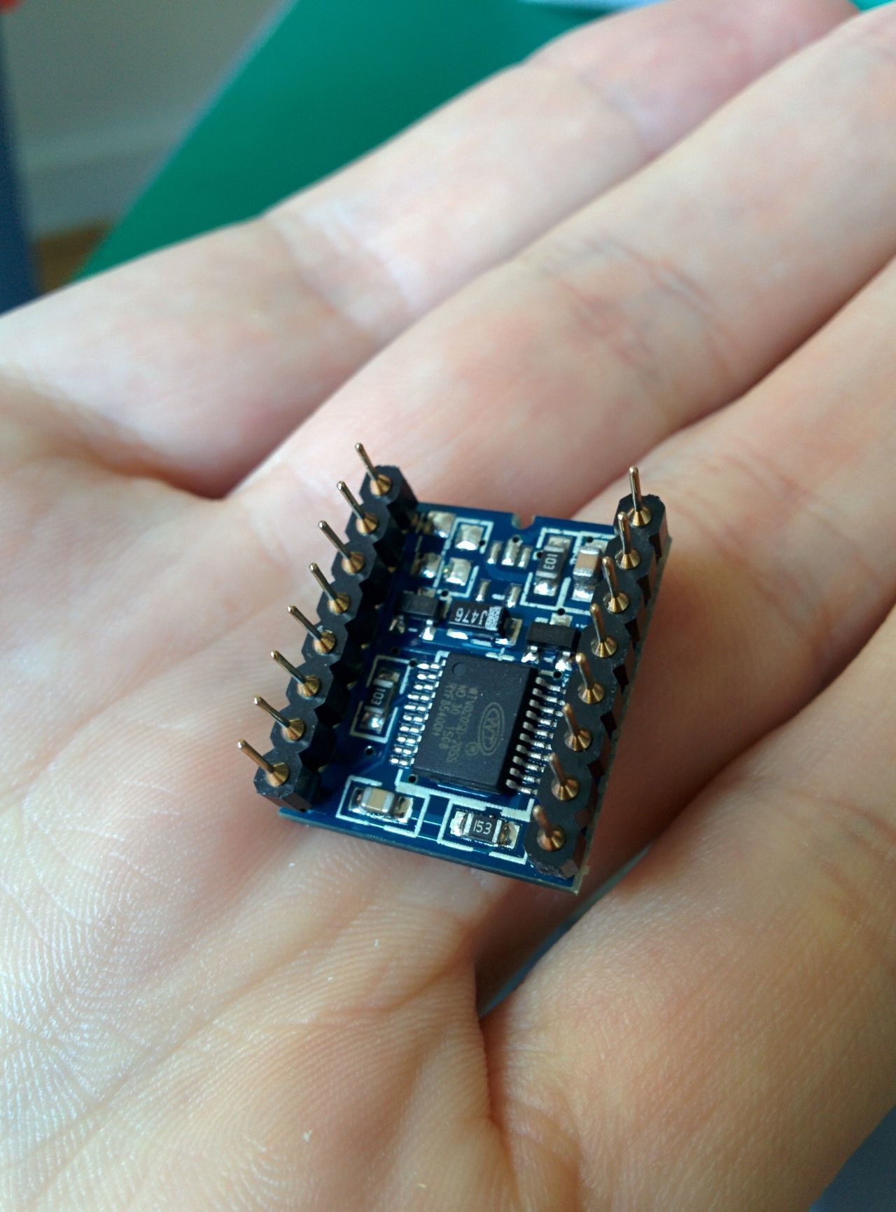
Unfortunately, this module cannot be used to write files on the micro-sd card; it has to be done with a computer. I will not be able to download new files through the internet directly with the connected object.
This module can be used to play audio files directly with buttons connected on the I/O, but also controlled from a "data" pin (look in datasheet for "Two line serial mode").
The sound output of this module is not great, but enough for my project :)
The module I ordered work with 5V or 3.3V depending on a soldering bridge.
As I want to manage it with an ESP8266 (witch works on 3.3V), I will use it in the 3.3V mode.
This module have two output pins which can be directly connected to a speaker. If the volume output is too low, I will use a low voltage audio amplifier (LM386 ?) with a variable resistor[1].
Important remark: As the module is cheap and old, only non-HC SD micro-cards can be used. Basically, any card below 2GB should be OK.
And even with that, some folks had to add a power supply wire directly on the SD card.
Before going further, read the blog post about WTV20 SD card and audio files creation.
In the meantime, you can use AD4 sample files.
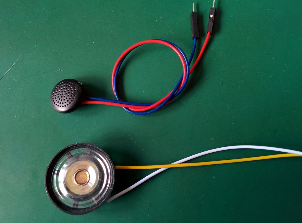
Speaker
The datasheet indicates that a speaker of 8, 16 or 32 Ohm 0.25W rating can be connected.
However, in a response to a post on the 4D systems forum, the 4D Systems technical people made the comment: "Speaker: 8 ohm 1W (Not recommended), 16 ohm 0.5W, 32 ohm 0.25W".
I bought a 8Ω / 0.5W speaker, hopping that it will work !
For my tests, I also used some old cheap earphones.
Other
- A micro SD-card (non-HC);
- Some cheap LEDs in 3mm and 5mm;
- Some resistors;
- A cheap Chinese wall AC/DC 5V converter[2];
- A 5V / 3.3V converter (AMS117-3.3 or 662k ?)[2:1];
- A micro-usb female plug[2:2].
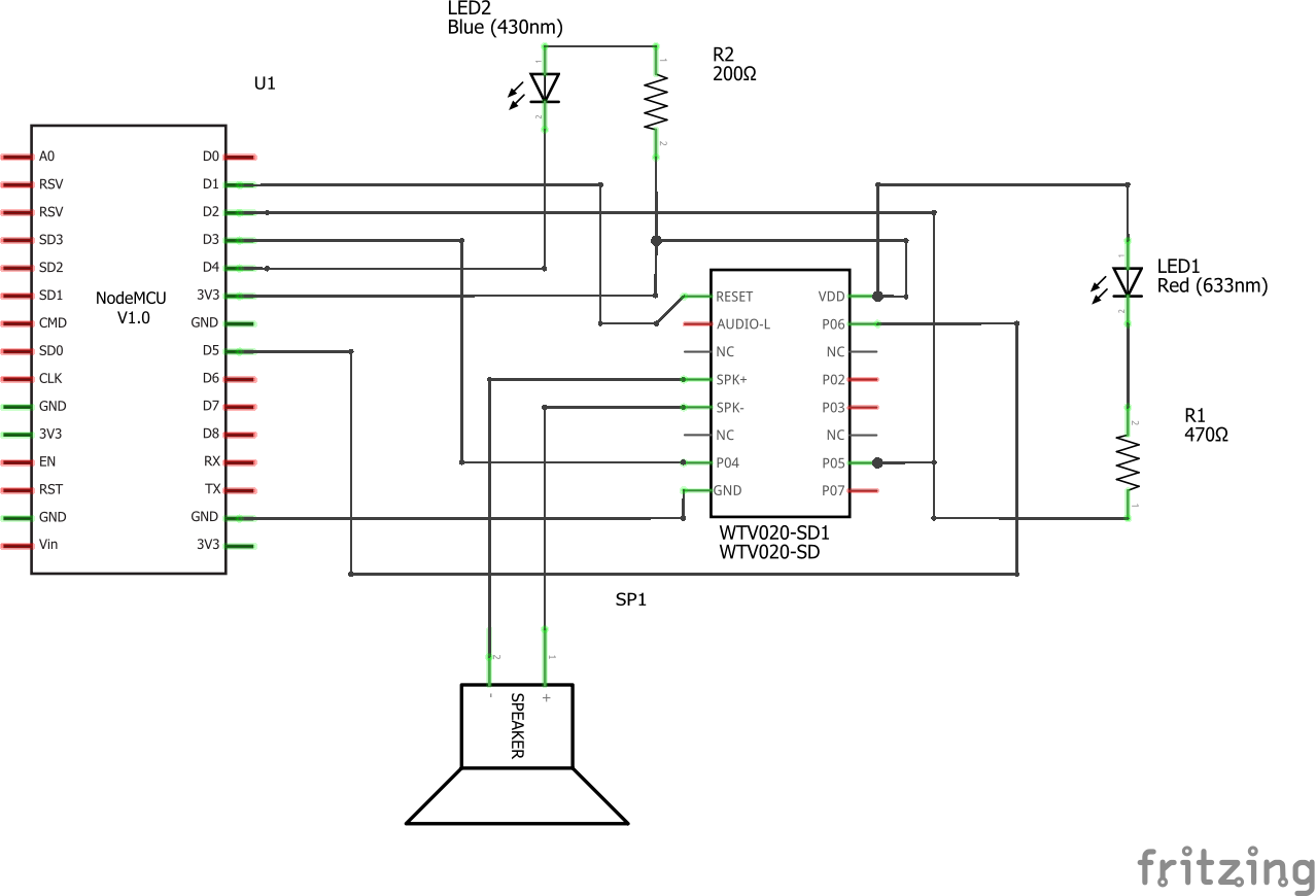
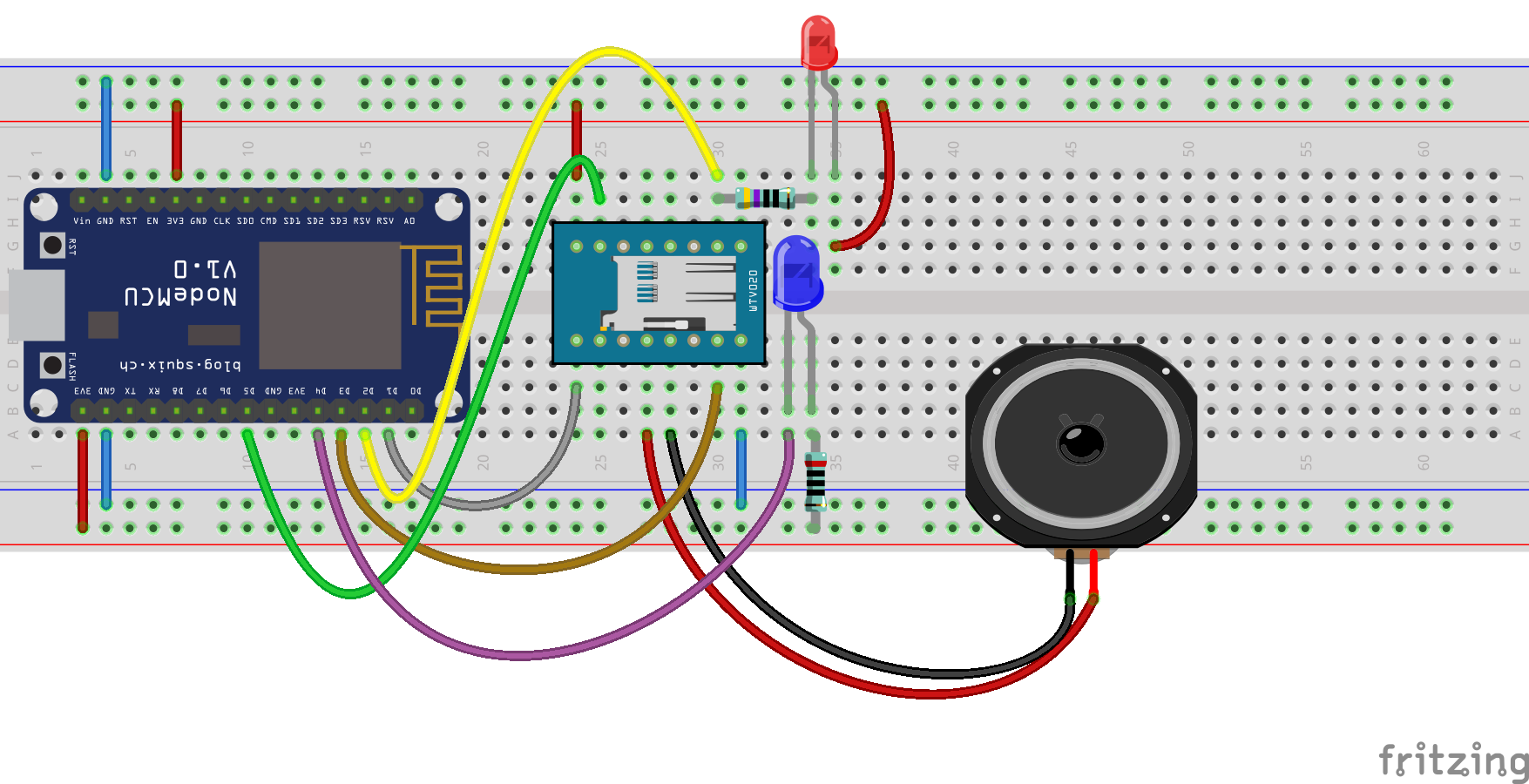
First circuit
This circuit is made with the NodeMCU dev board.
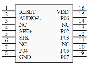
WTV020-SD-16P pinout
The "two line serial mode" allows to send some commands to the WTV020 (volume, play, pause, stop, music selection).
I/O function in two line serial mode
| I/O | P02 | P03 | P04 | P05 | P06 | P07 |
|---|---|---|---|---|---|---|
| Function | K1 | K2 | CLK | DI | BUSY | K3 |
| Trigger | NEXT* | PREVIOUS* | ------ | PLAY / STOP* |
*: Not used in the circuit
Module pinout
Extracted from the datasheet
LED pulse
As I said before, I want to pulse a LED as a Tardis reminder.
For that, I used a PWM output of the ESP8266, and connect the LED through a resistor.
On breadboard
This first circuit connects the NodeMCU devboard to the WTV020.
This module have a pin dedicated to the busy output state (high = busy). As the datasheet suggests, I added a LED (3mm, red) to display the status of the module.
Moreover, I read this state with an ESP input pin.
A lot of schematics on the Internet turn on the LED for the "idle" state. I prefer light up the LED only on the "busy" state.
Circuit
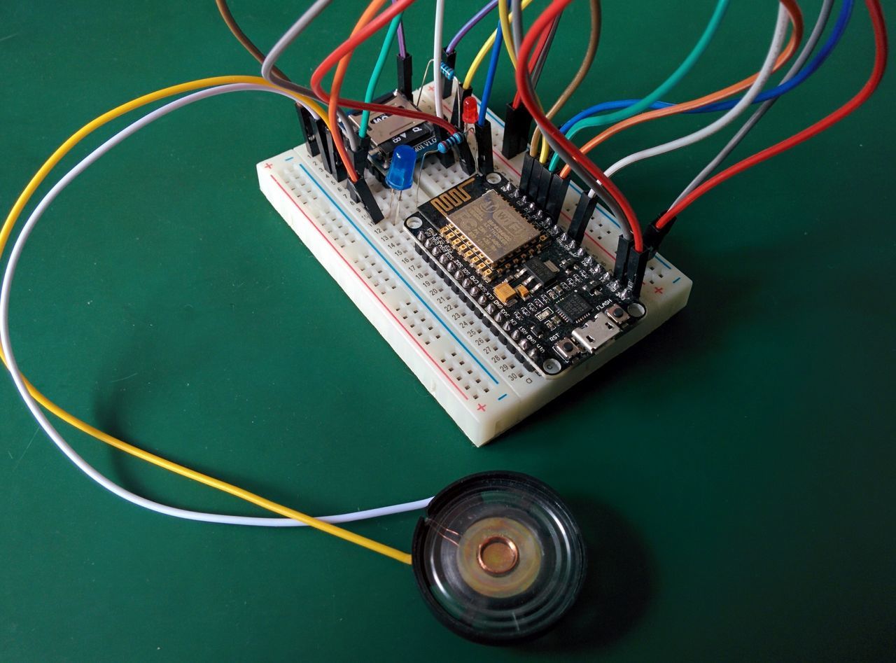
Pictures
Source code
Unlike the first test of the ESP8266, where I used NodeMCU, I wanted to try the Arduino framework for the ESP8266.
The template is quite simple :
#include <Arduino.h>
#include "ESP8266WiFi.h"

void setup() {
  Serial.begin(115200);
  Serial.println("Setup done");
}

void loop() {
  // Code executed after "setup()", in loop
}
LED pulse
I want to create a LED pulse without any call to the delay() function.
The value of the LED to set with analogWrite() is function of the time (millis()).
The best way to get the value to set on the PWM pin, is to use the sinus function (sin()). But the range of analogWrite() is between 0 and 255 for AVR, between 0 and 1024 for ESP8266. Moreover the pulse period must be around 5 seconds.
Pulse base signal: sin( millis() )
Range 0-1024[3]: sin( millis() ) * 512 + 512
Period of 2s: T = 2π / a = 2s with sin( a * t ) so sin( 2π / 2000 * millis() ) * 512 + 512
And to begin with the pulse with led off (i.e. f(pulseBeginTime) = 0),
sin( 2π / 2000 * (millis() - pulseBeginTime) + 3π / 2 ) * 512 + 512
IDE
For this project, I will use PlatformIO, which I discovered few days ago.
At the moment, PlatformIO (v2) doesn't manage different versions of libraries. So, please be careful, the following code will use these dependencies:
- Platform "expressif" with Arduino/ESP8266@2.1.0
- Library PubSubClient@2.6
- Library WiFiManager@0.12
- Library Json@5.6.2
Source code
Available on GitHub :

Result and next step
IT WORKS !
But... The WTV020 freezes sometimes, and I don't know why.
Now, I will try to use a standalone ESP8266, without the big NodeMCU board.
I tried that, but the result was not better than without the amplifier. Maybe I did something wrong, or the voltage was not important enough. I don't have enough experience on those IC. ↩︎
Those components will be used to the final product. In this post, I only use the NodeMCU devkit board. ↩︎ ↩︎ ↩︎
For the ESP8266, the maximum analog value is "1024", and for an Arduino board it's "512". ↩︎