Blinking wearable
This project was the opportunity to order some PCB and discover some new components as hall sensors.

In this blog post, I will talk about a blinking device I built as a Proof of Value (PoV).
The concept is quite simple:
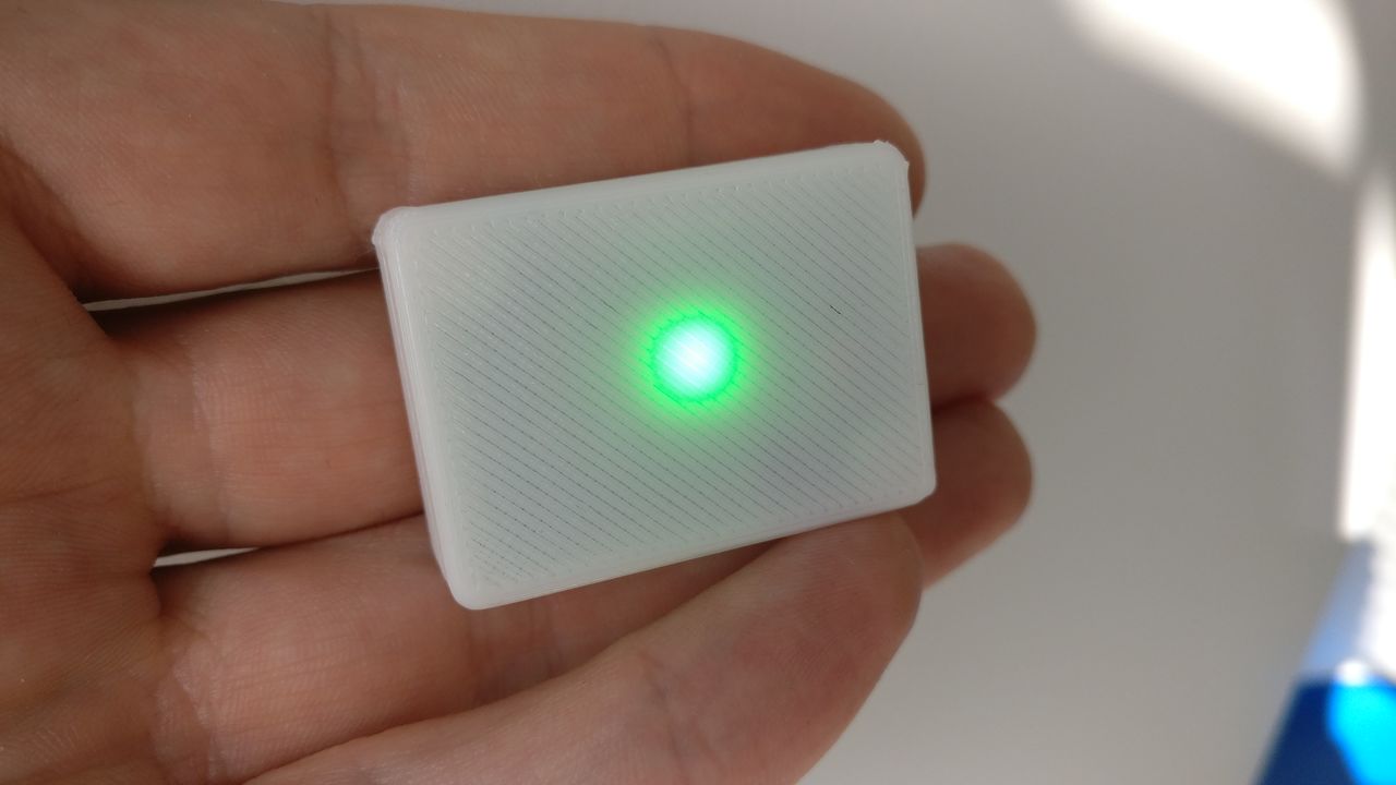
- The device should blink in green during 2 hours,
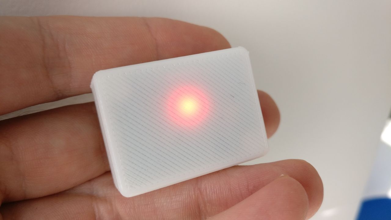
- After two hours, the device should blink in red,
- After two more hours, the device should stop blinking,
- The time counter can be reset with a magnet near the device.
The device should be as small as possible, as it should be wear and visible.
I will try to create a real PCB. It will be my first!
Selected components (at the end)
I tried to use SMD components. As I have to solder them by hand, I used the 1206 package (3.2mm × 1.6mm), as they are quite easy to solder by hand.
MCU
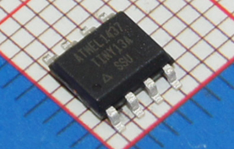
I chose an ATtiny13A. It is inexpensive, low power, and has more pins as necessary.
To be able to use it's tiny memory, I will not use the Arduino framework, but directly use the AVR SDK.
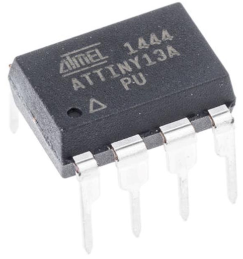
On the PCB, I will use the SSUR package:
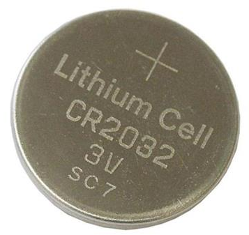
Battery and battery holder
As I want a compact format, and have around 3V, I chose to use an CR2032 battery, which has a stable discharge curve.
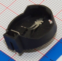
I had to chose an holder. I ordered few types.
At the end, I chose the cheap white SMD. Not sure it is the right choice, as with this choice, I will have SMD components on both sides of my PCB.
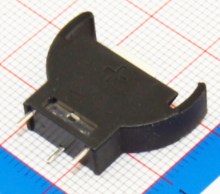
Big holder - through-hole
Too big for my purpose. I want my device to be as flat as possible.
Perpendicular holder - through-hole
Not suited for my PCB.
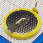
Battery with soldered leads - through-hole
I think it could be a good solution for a disposable device. Not for the first iterations though.
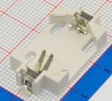
Cheap SMD
I think it's a good compromise. I used this one for my first PCB.
LEDs
As I want to have all the LED near each other, I chose a SMD LED package containing 3 LED in one. The size is 5050 (5mm side). Not easy to solder but easy to use.
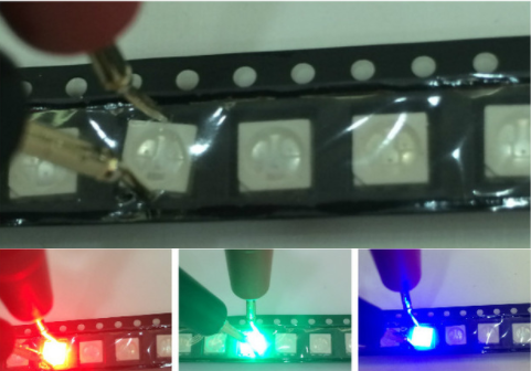
This package is quite easy to use, as the 3 colors behaves as standard single LEDs.
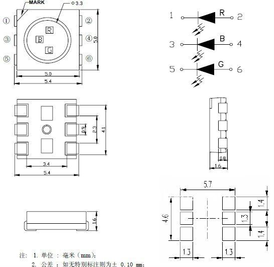
Note: I still didn't received the LED yet, so I used other SMD leds
Decoupling capacitors
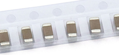
- 0.1µF ceramic capacitor (un-polarized) near the MCU, with the 1206 package (to be easy to solder)
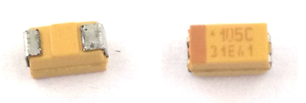
- 10µF tantalum capacitor (polarized) near the main power.
Sensor
I found 3 options to sense the magnet:
- Reed switch
- Magnetic sensor (two chips selected)
- Hall sensor
Reed switch
I wanted to use this sensor, but I have an issue: I broke three of them, tying to bend the pins.
Moreover, it seems that the soldering can affect the sensitivity of the component.
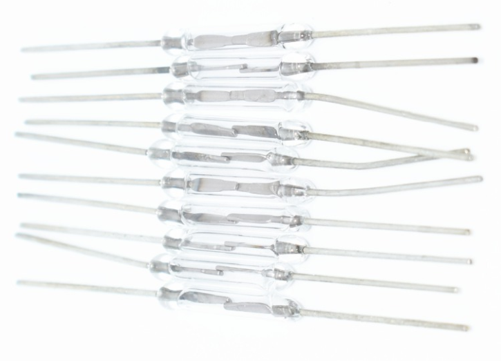
Dimensions: 14mm x 2mm
Other versions exists, which is protected by a plastic box, but I read that it is still fragile.
I will use this sensor switch for my first PCB, but I will also test some other solution, more expensive, but also more reliable.
I also have some difficulties to find some small + cheap + SMD + low quantities reed switch.
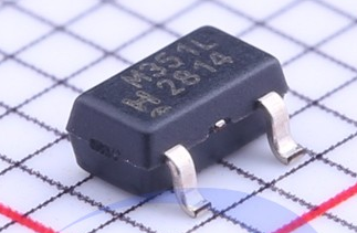
Magnetic sensor: Honeywell SM351LT
Magnetoresistive sensor IC, high sensitivity (7 G typ.), nanopower, SOT-23 package.
- Push-pull output (no pull-up resistor required)
- For applications requiring ultra high magnetic sensitivity (7 Gauss typical operate, 11 Gauss maximum operate) and a very low current draw (360nA typical).
- Operate Point 3 G min., 7 G typ., 11 G max.
- 1.65V min., 1.8V typ., 5.5V max.
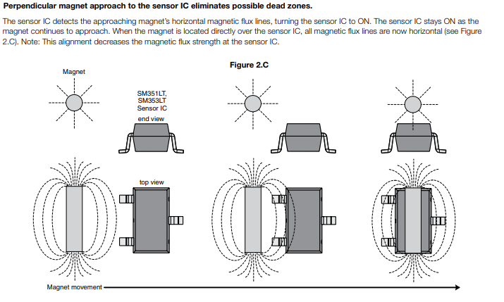
The ideal magnet alignment is not really in phase with my project:
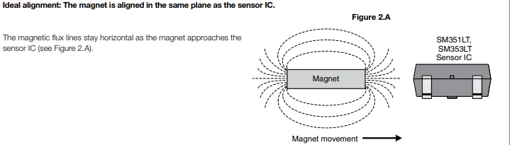
But it still works in other configuration:
Hall sensor: Honeywell SL353LT
SL353 Series micropower omnipolar digital Hall-effect sensor IC, high-duty cycle, low power (0.33 mA, 2.8 Vdc), SOT-23 package.
- Push-pull output (no pull-up resistor required)
- Extremely low current drain (1.8µA)
- 2.2 Vdc min., 2.8 Vdc typ., 5.5 Vdc max.
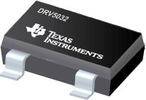
Hall sensor (Texas Instrument DRV5032)
The DRV5032 device is an ultra-low-power digital-switch Hall effect sensor, designed for the most compact and battery-sensitive systems.
- 5-Hz Version: 0.54 µA with 1.8 V
- 1.65- to 5.5-V Operating VCC Range
A lot of options are available:
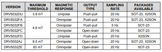
As I'm looking for an omnipolar version, with low power consumption, I chose the DRV5032FB version.
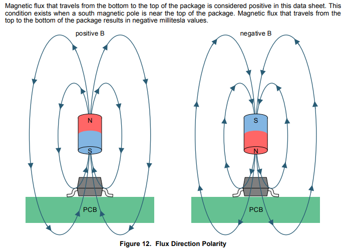
The magnetic sensitivity is not the same as the magnetic sensors that I listed before:
Others
- 3x 100Ω resistors to limit the current in the LED. I used the 1206 package.
Note: I should use a smaller value for the blue LED, but it was easier that way, and the blue LED is more a debug LED than anything.
Circuit
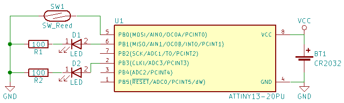
First iteration
At first, I used 2 LEDs to display the state of the device.
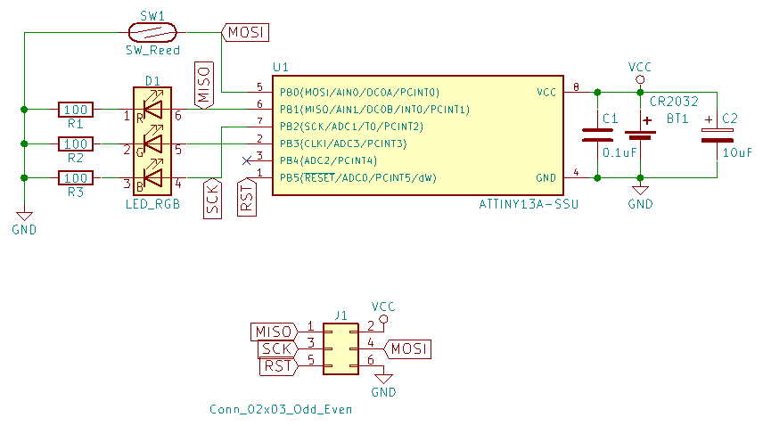
Second iteration
- I added a LED and some decoupling capacitors.
- This design use the 5050 RGB LED (and use another PIN for the blue LED).
- I also changed the pins for the LED to simplify my PCB design.
- A changed the ATtiny13 package for the SSUR
Source code
The source code is available on Github.
As I'm using the ATtiny13A with low flash, I tried to use as less Arduino function as possible.
For example, I didn't use the pinMode(), digitalWrite() and digitalRead() functions, but I used the datasheet to write into the dedicated registers.
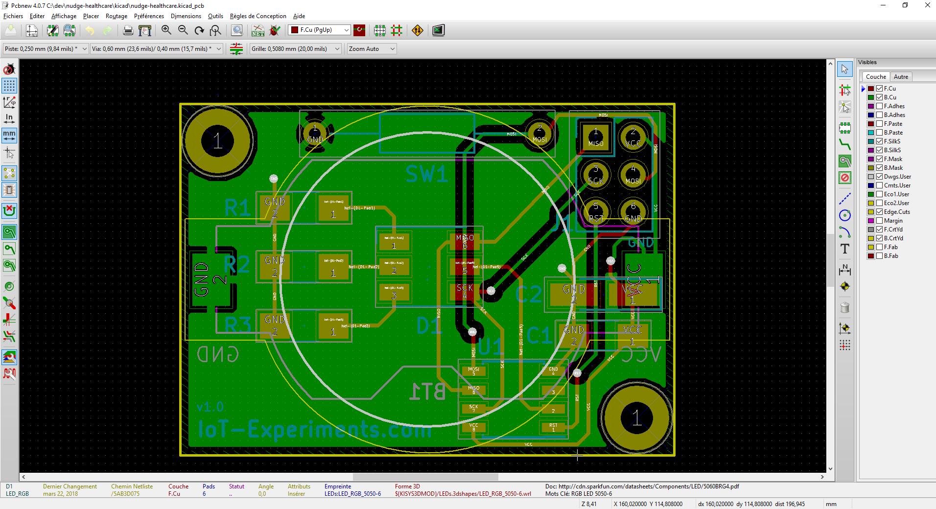
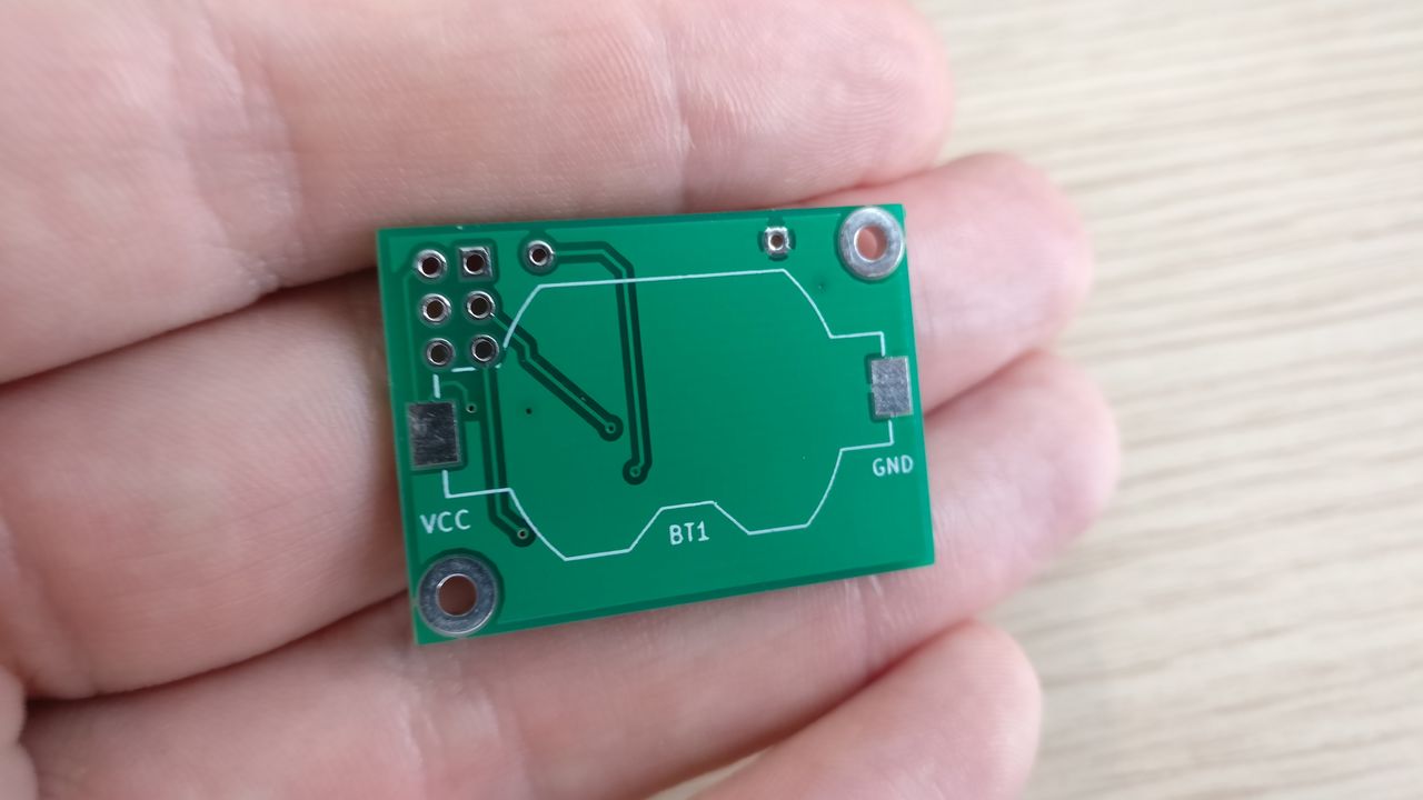
PCB design
I created a PCB for the first time, with Kicad which is quite easy to use when you know the shortcuts.
I watch some Youtube videos to understand how to use Kicad: Eric Peronnin (in French).
And some videos to avoid some basic mistakes: EEVBlog
This PCB uses 2 layers.
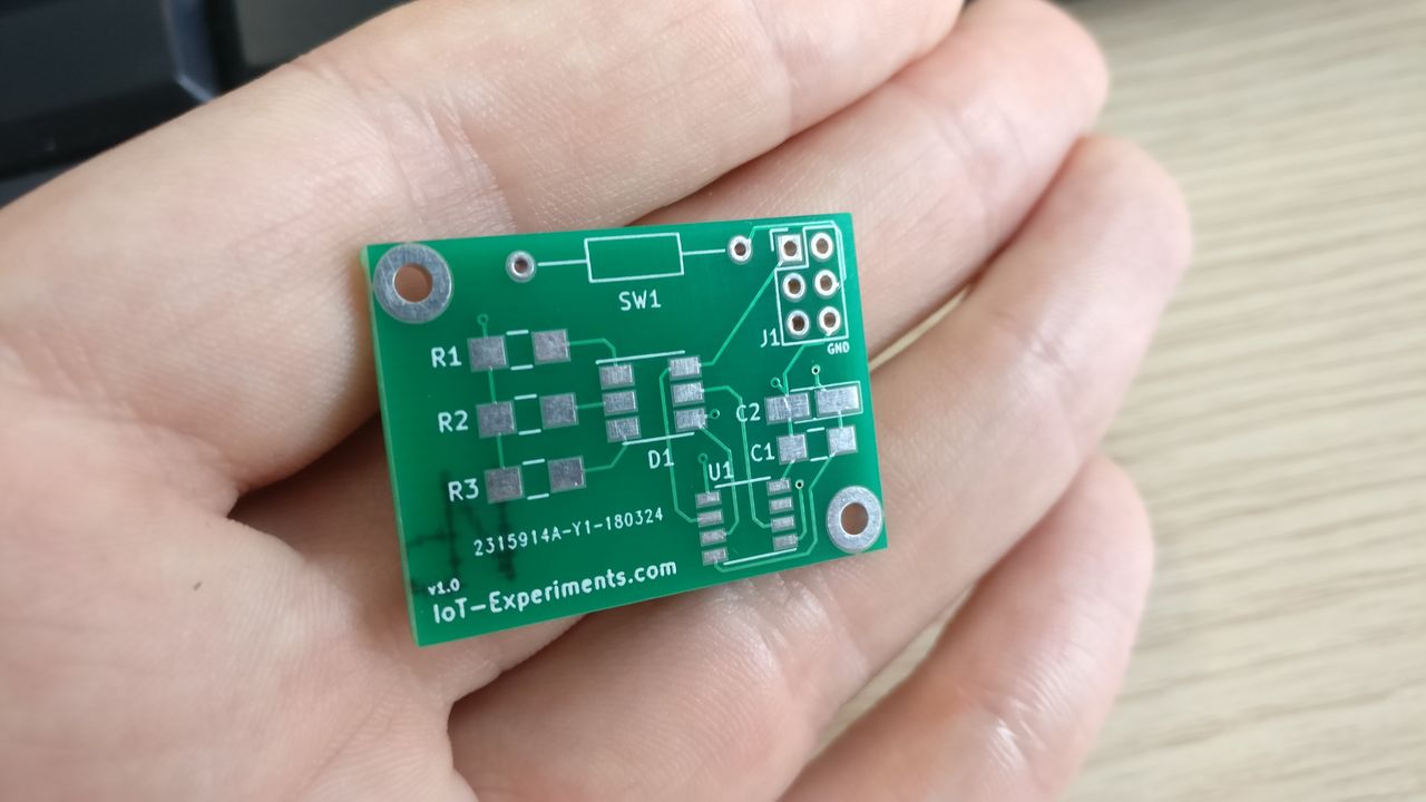
I then ordered some PCB ! I was so happy when I received them !
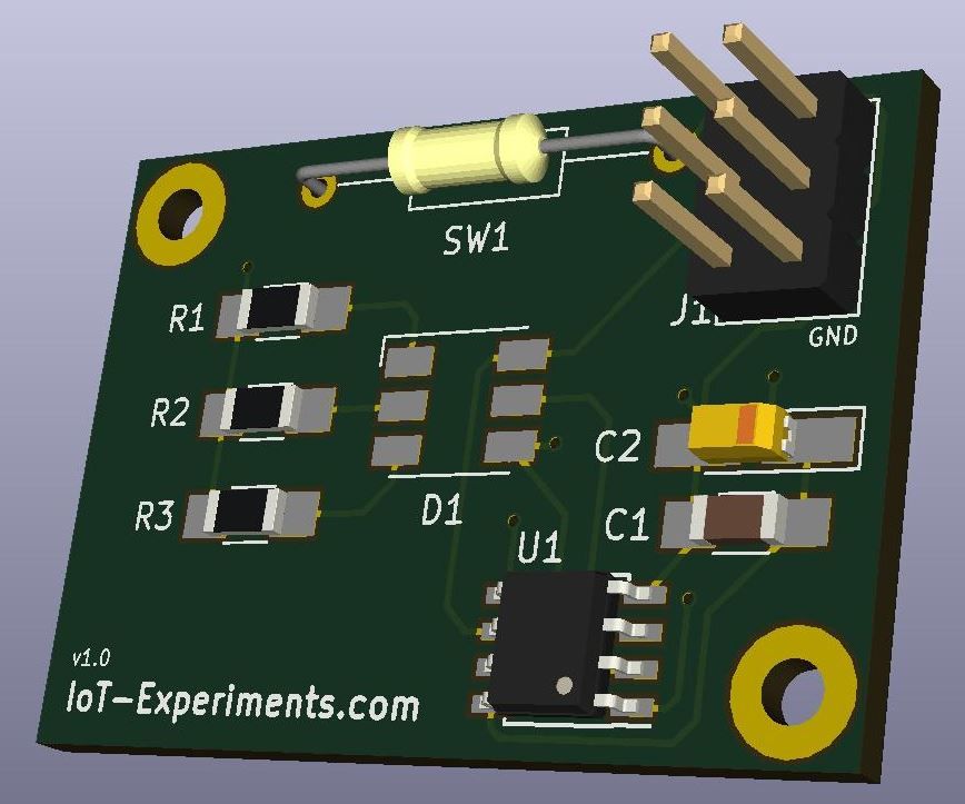
PCB Front
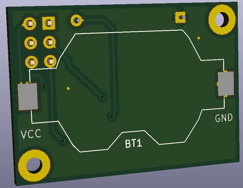
PCB Back
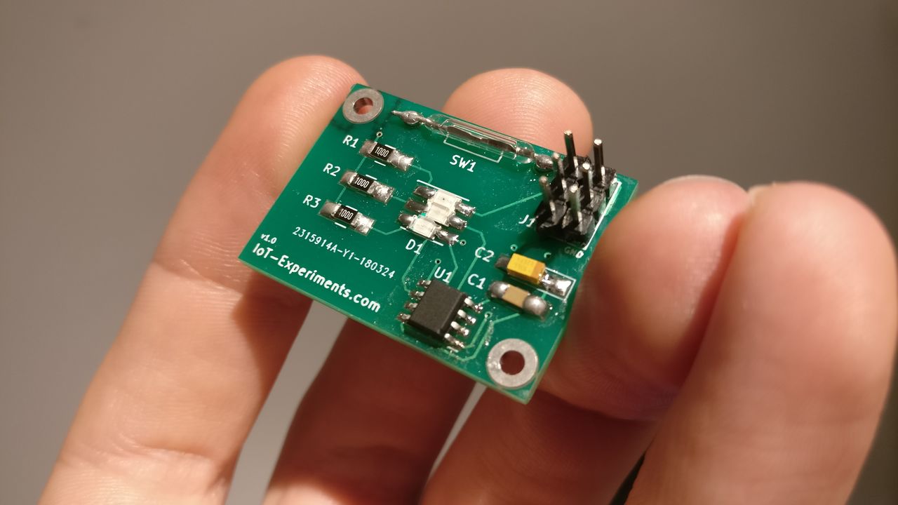
After soldering the components, I already learned few things:
- Not a good idea to rotate the MCU at 180°, as I forgot that, and soldered it in the other way.
- I should add a reverse polarity protection circuit
- As I said before, the reed switch is not a good idea: it take a lot of space on the PCB and is too fragile. At the end, I soldered it without bending the pins.
- Not a good idea to use SMD component on both sides of the PCB
PCB with components
It was quite easy to solder the components, with the exception of the reed switch.
As I didn't received the 5050 LED yet, I used some SMD LED (green, red, blue).
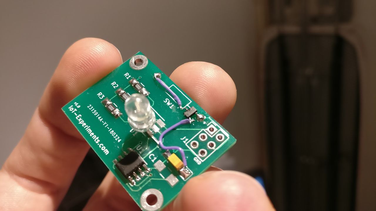
I also created another version with the SM351LT, with a wire between Vcc and the Vcc pin of the chip. Don't look on the big LED, I was out of SMD LED.
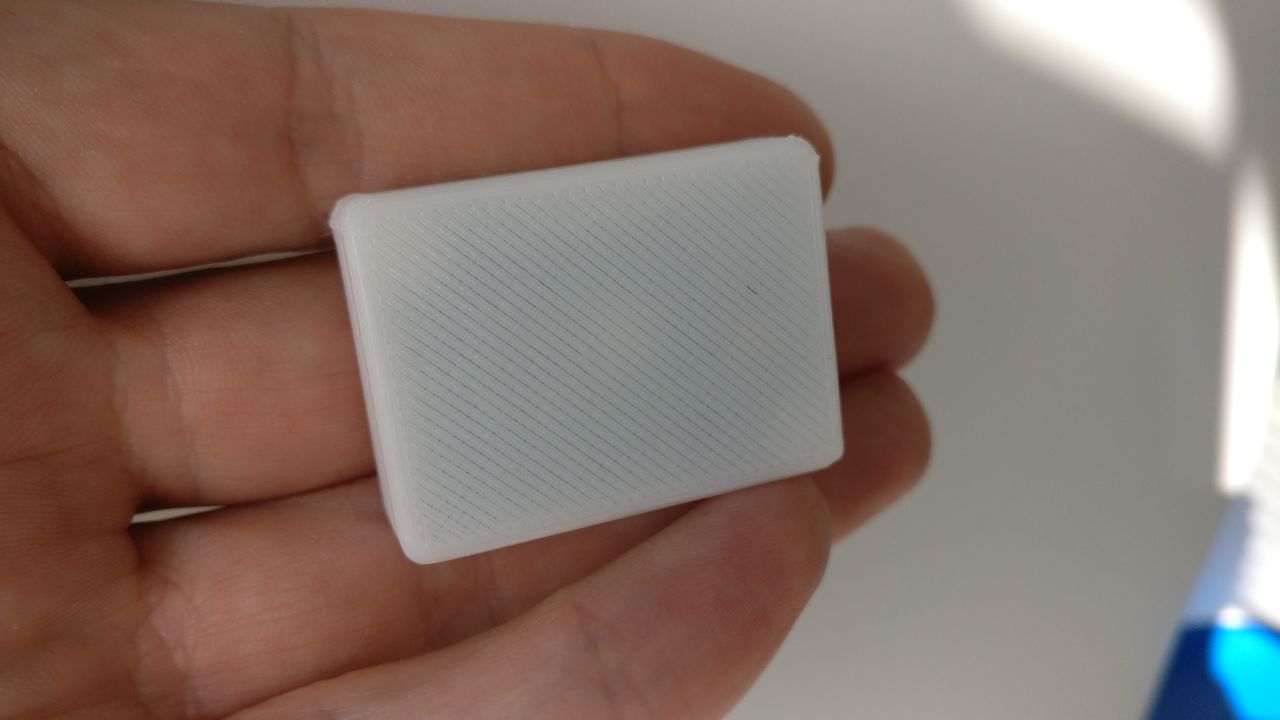
Case
I un-soldered the 6 pin header to add the circuit to the case I printed.
Circuit case
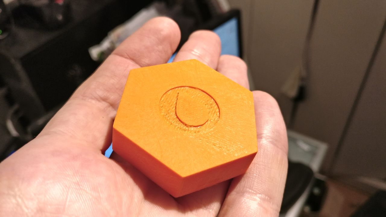
Magnet case
I created a few versions of a device for badging the wearable. Each one have a hole under it to put the magnets.
I printed them in ABS, to be able to cold vapor-smooth them.
Option A
Option B
Power consumption
Note: The LEDs are still working at 2.2V.
Reed switch
- 3.8µA @ 2.2V
- 4.2µA @ 3V
So, without taking the consumption during LED pulse phase, with the 220mAh battery we should have around 2400 days (220 / (3.8 * 10-3) / 24). I think that the battery will last easily more than one year.
SM351LT
- 4.5µA @ 2.2V
- 5.3µA @ 3V
Not very far from the reed switch, and more reliable and compact.
SL353LT
- 6.3µA @ 3V
Not very far from the SM351LT. The detection range is about the same.
However, I'm not sure that the magnet polarity has an impact on the sensor.
Conclusion
The device can already be used to test the value of the product.
It will last more than one year on batteries, which is more than enough for this first iteration.