Day counter on LCD display
Using an ATtiny and modifying an LCD module gave me the ability to build a low power display working more than a year with two AA batteries.
I prototyped a day counter for some friends. I was my first try with a dynamic LCD display, and an ATtiny.
The device I build is not a production-ready unit, but a Proof of Value (PoV); it will help my friends to test the concept and adjust it, or even abandon it.
As usual, I will order the components on Aliexpress.
Requirements
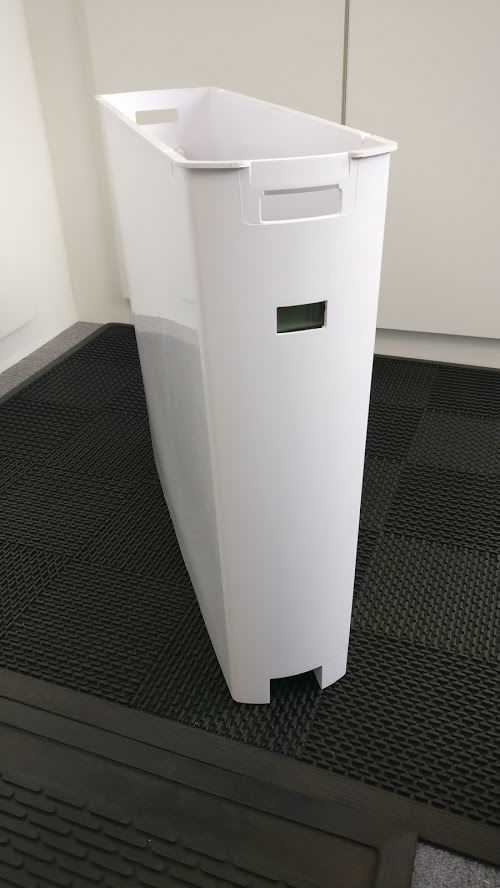
- The device will be placed in a small container,
- The display will have to be visible outside the container,
- A button will be placed at the bottom of the container,
- The device will be powered by cheap batteries (no LiPo batteries),
- The device will have to run on one set of batteries for more than one year,
- The display will show the number since the last button press.
Component choice
Batteries
I choose to use AA cells. They are quite cheap, and have a good amount of energy (around 2500mAh). With 2 cells, I will get between 3V and 1.8V.
Display
To be able to run during more than one year, I had to find a low-powered screen.
After some researches, I understood that an LCD display will do the job.
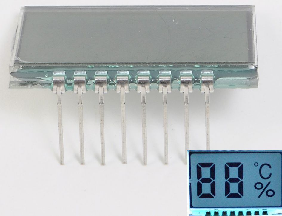
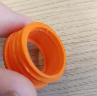
1st try : salvadged LCD display
At first, I tried to salvage the LCD display on a pen/clock (working at 1.5V) :

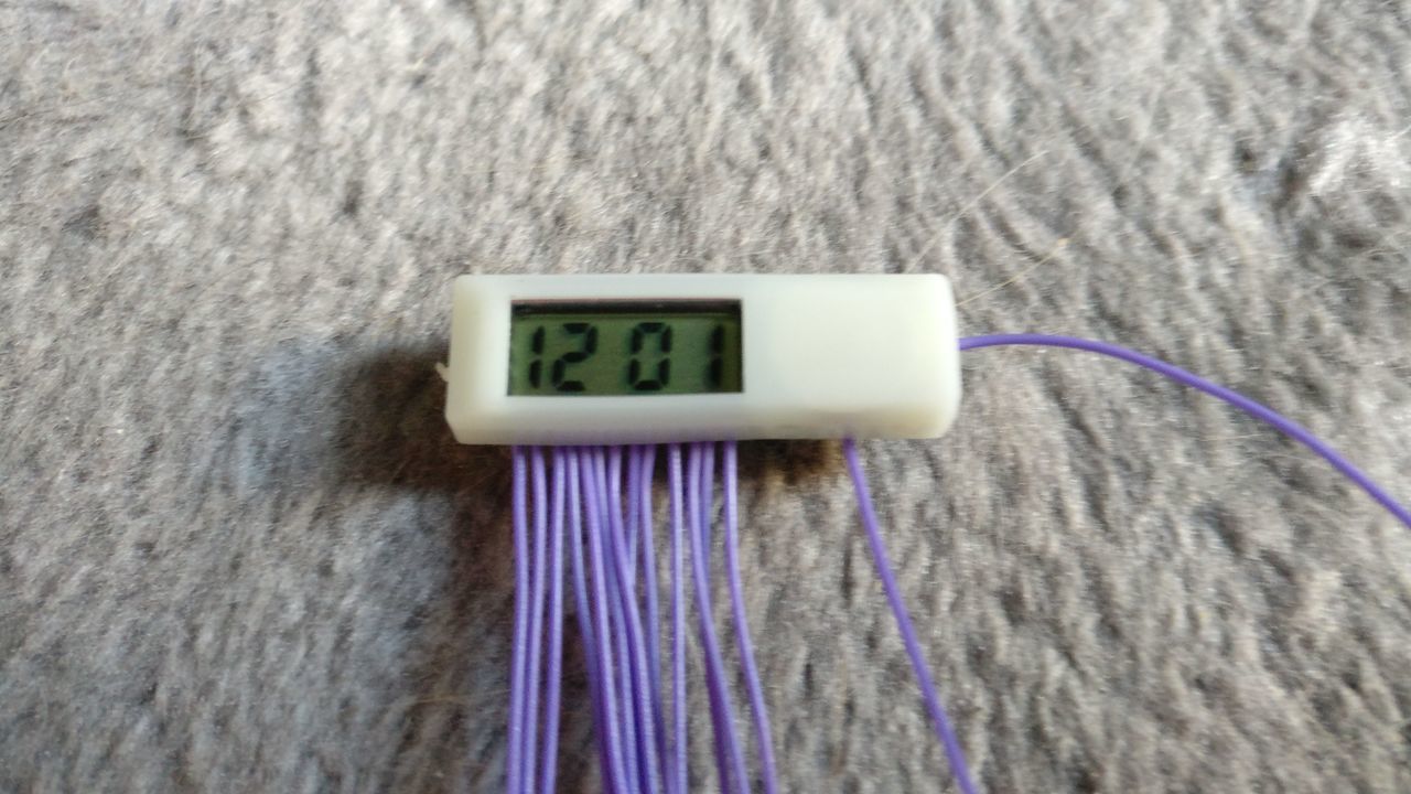
I tried to understand how the little chip on the PCB is driving the display.
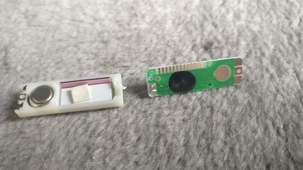
I added some wires on the PCB pins. There are quite small and connected to the display with an elastic band. It was quite a challenge !
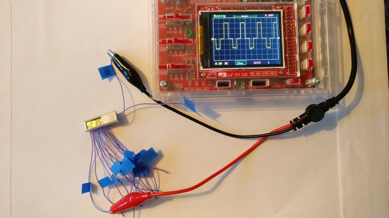
Sadly after trying to understand the levels and and the signal, I stopped : it seems to complicated for me to retro-engineer the signals.
2nd try : barebone LCD display
I then ordered some LCD displays. I discovered that you can buy static drive or dynamic drive displays.
The static drive works a little like 7 segments LED. You have to power each segment continuously to light them. These displays have a lot of pins.
The dynamic drive uses some common pins as selector to power on / off some segments, quickly enough to fool our eyes. I will not explain it here, at it's quite complex and not the goal of this blog post.
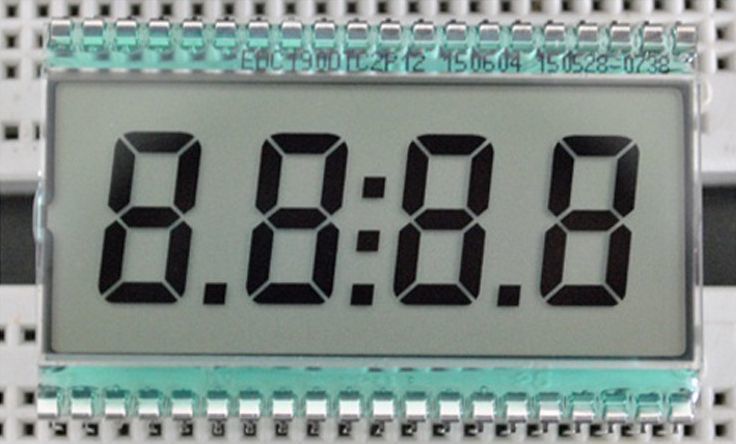
As the dynamic drive does not powered every segment in continuous (and should use less current), and need less pins, I bough the following display (working at 3.3V) :
I thought that I would be able to drive them with a barebone ATMega328p, but after few researches after receiving the display, I seemed too challenging (again !).
And using a separate chip as a driver is beyond my skills (package of the chips is to compact to be soldered by myself).
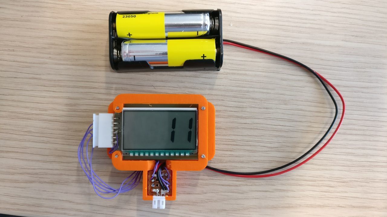
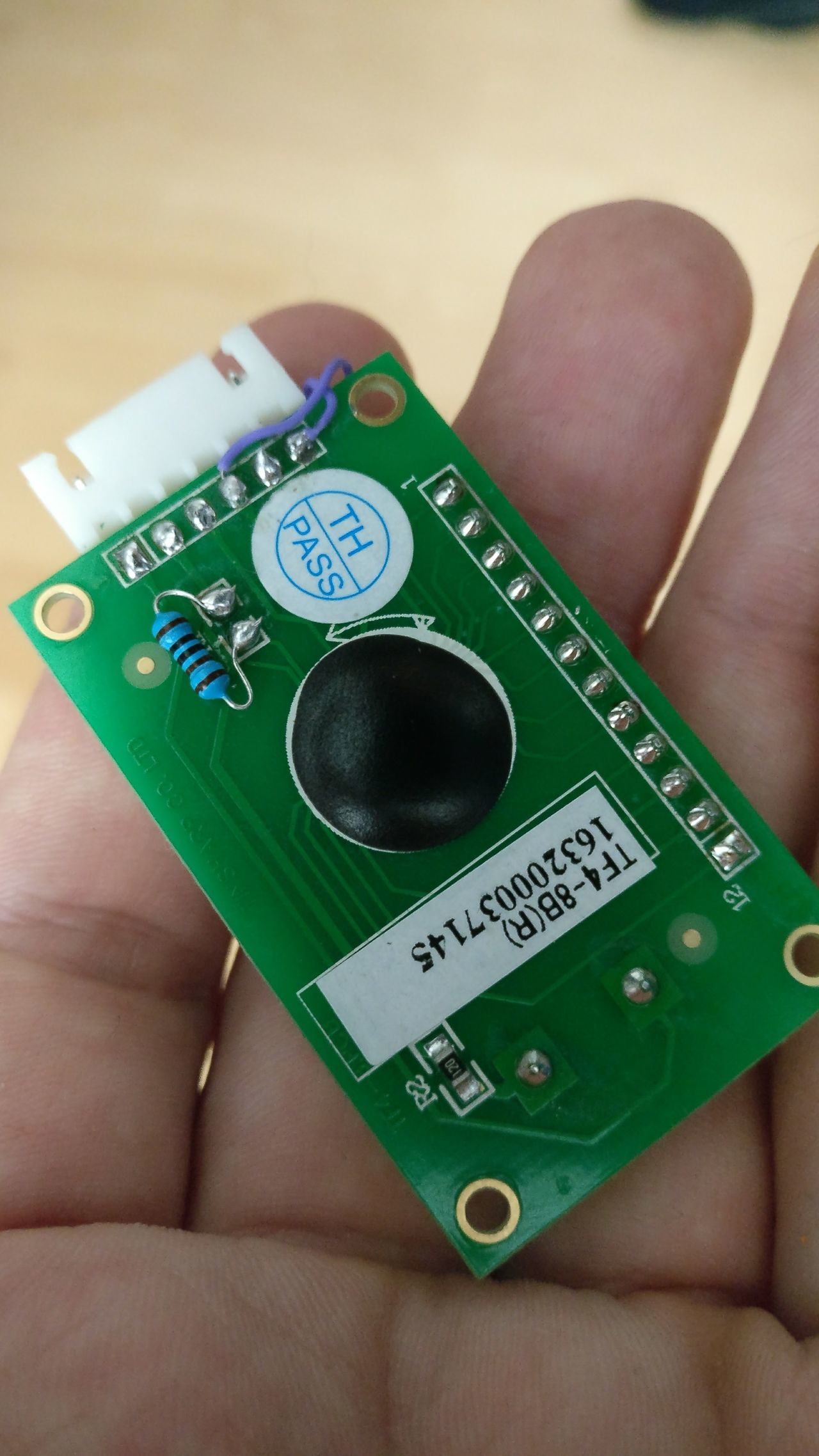
3rd try : LCD display with driver
Last solution : use a LCD display with a driver on a PCB.
I found only one cheap display, working at 5V and 3.3V (by changing a resistor) :
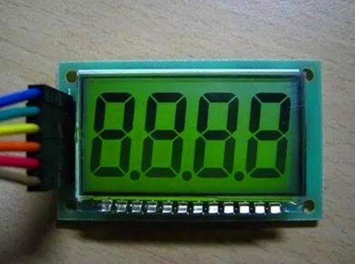
It seemed to work with a driver similar to an HT1621 (datasheet). With SPI, you write some values in the RAM of HT1621, and the driver will use them to turn on / off the segments of the display.
So, you can have a MCU sleeping at very low current, with only the LCD driver and the LCD screen consuming current.
Main MCU
To use my LCD screen, I looked for a chip able to run at low current and low voltage. I found the ATtiny85, below 2€ :
- Active Mode: 1 MHz, 1.8V: 300 µA
- Power-down Mode: 0.1 µA at 1.8V
It has enough pins to drive my LCD display and receive a button pressed event. Moreover, at has some interrupts to be awaken when the button is pressed.
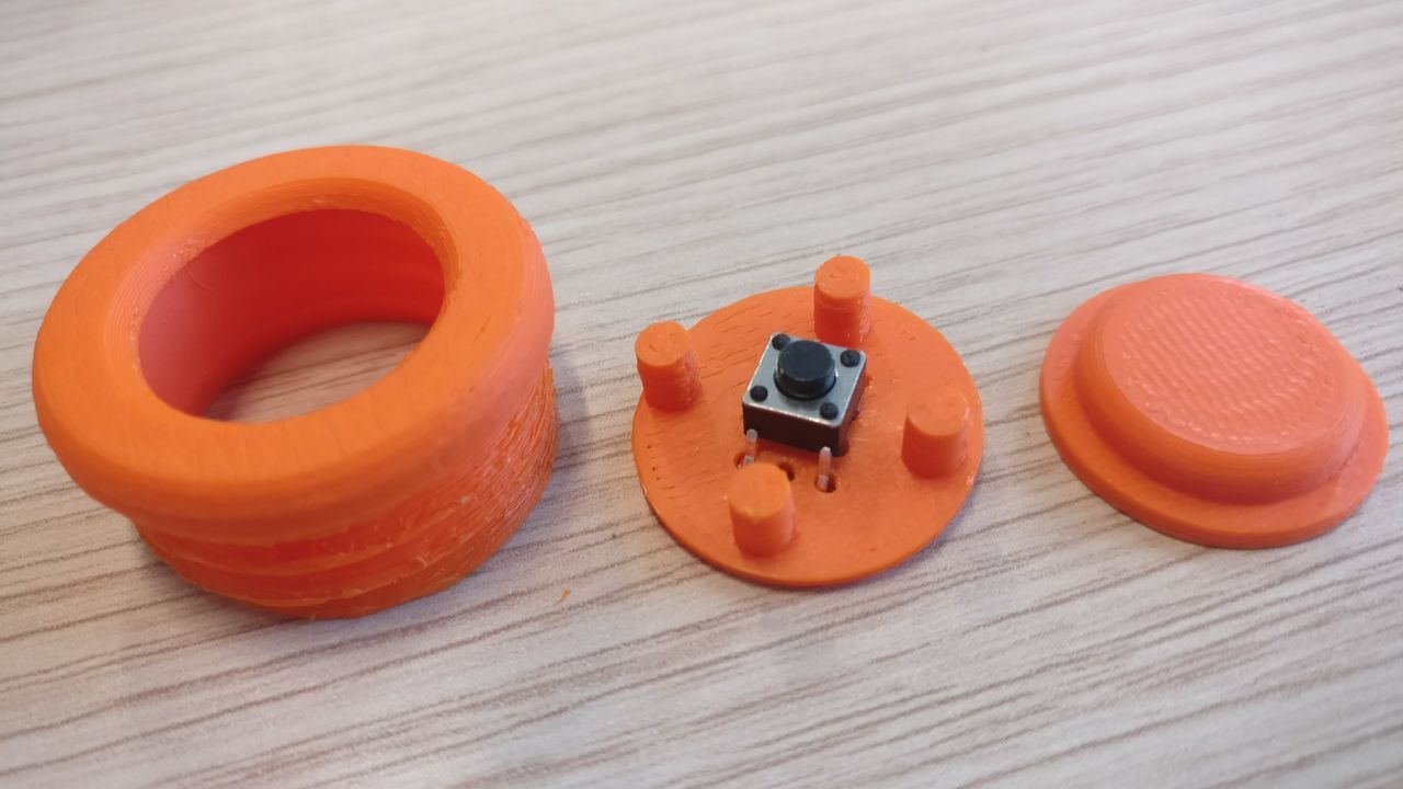
Button
I used a very small switch (6 * 6 * 4.3mm), quite cheap, and I build a 3D printed case. I had to print a lot of prototypes before getting the perfect button, without any supports, and assembled without any glue.

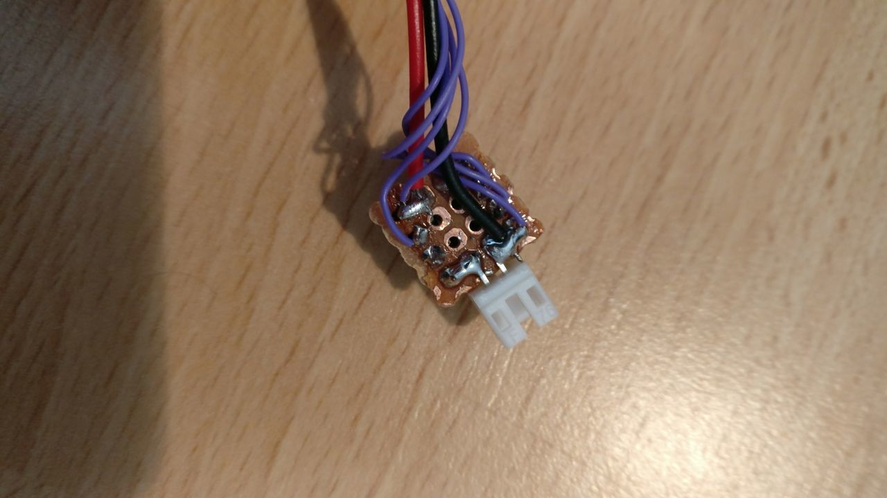
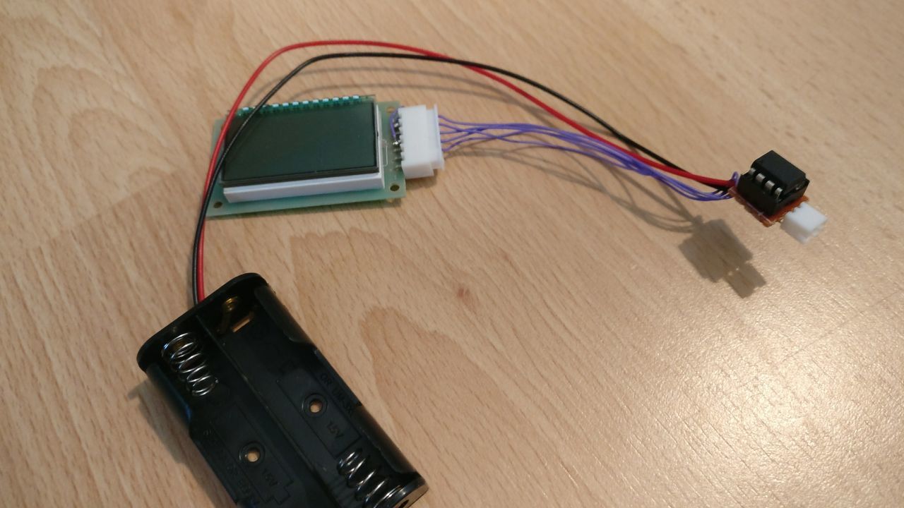
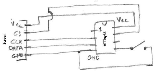
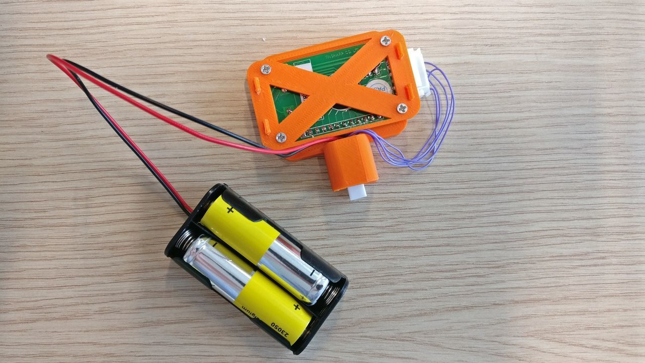
Circuit
The circuit is quite simple.
First of, I had to change one resistor (57kΩ to 1kΩ) of the display to be able to use it at 3.3V. I also added a connector on the screen.
I also used a little connector for the button.
The whole is soldered on a prototyping PCB.
Schematics:
Programming
ATtiny @ 1Mhz
To run the ATtiny at 1Mhz, I used avrdude, an USBTinyISP and a custom PCB to flash the chip.
Once the circuit ready, use the following command to change the fuses of the ATtiny85 :
avrdude -c usbtiny -p t85 -Uhfuse:w:0xDF:m -Uefuse:w:0xff:m -Ulfuse:w:0x62:m
Flash the ATTiny
To flash the ATtiny, I used platformio, an USBTinyISP, and a custom breadboard. After programing, I placed the programmed ATtiny on the circuit.
Source code
The concept is quite simple : sleep and wake up to increment a counter every day, or when the button is pressed to reset the counter.
I used the Arduino stack, as it's easier than C code and Atmel stack.
For me, it was quite complex to develop, as I never used interrupts before.
External Interrupts
On the ATtiny, external interrupts allows you to be woken up even in power-down mode (less consuming sleep mode).
You have two external interrupt types :
- Falling / rising edge interrupt: raised when the pin toggles from low to high / high to low
- Level interrupt: raised when the pin is held down to a specific level (low / high)
It's important to distinguish the INTx and PCINT. On the ATtiny, you have a INT0 pin: it can detect low, rising, falling conditions, and is linked to a dedicated vector / handler.
The PCINT-able pins can only detect low-high / high-low transition, and have a common vector / handler.
For my device, I used the PCINT pins, and I managed the state of the switch into the main loop to debounce it.
I didn't use the INT0 interrupt, because even if the INT0 interrupts can be triggered by a falling or rising edge or a low level, in power-down mode, only low level interrupts can be used.
Sleep mode
To use less current as possible, I choose to use the power-down mode. It has some restriction (external interrupts, internal clock), but the ATtiny85 only consumes 0.1V @ 1.8V & 1Mhz.
The ADC is also disabled as it isn't used.
Wake-up by watchdog
To check if the 24h delay is reached, and as the timer doesn't have to be precise, I used the watchdog with the maximum delay: 8 seconds.
When activated, the watchdog will call a dedicated vector every 8 seconds.
Internal clock
At first, I used the internal clock to manage the 24h delay (with the millis() function). Sadly, I didn't saw that on power-down mode, the clock is not enabled.
To check if the delay is up, I count the number of wake-up, as I now that the device is woken up every 8 seconds.
If the number of wake up is equal to 10800 (24 * 60 * 60/8), it means that the device has been up for 24h. The counter of wake up is reset, and the day counter is incremented, and sent to the screen driver.
Button pushes
When the button is pushed, the vector is called, but the information is managed in the main loop.
I added a demo mode: when the button is pushed more than 5 seconds, the watchdog will be configured at 1 second, and the day counter is incremented each time. It becomes a second counter :)
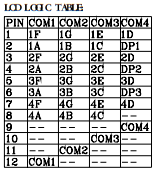
Drive the screen
To drive the screen; I used a library that I found online. The only thing I had to do, is create the binary array to display each number.
For that, I used the extract of datasheet of the screen (TF4-8B):
The source code is available on github

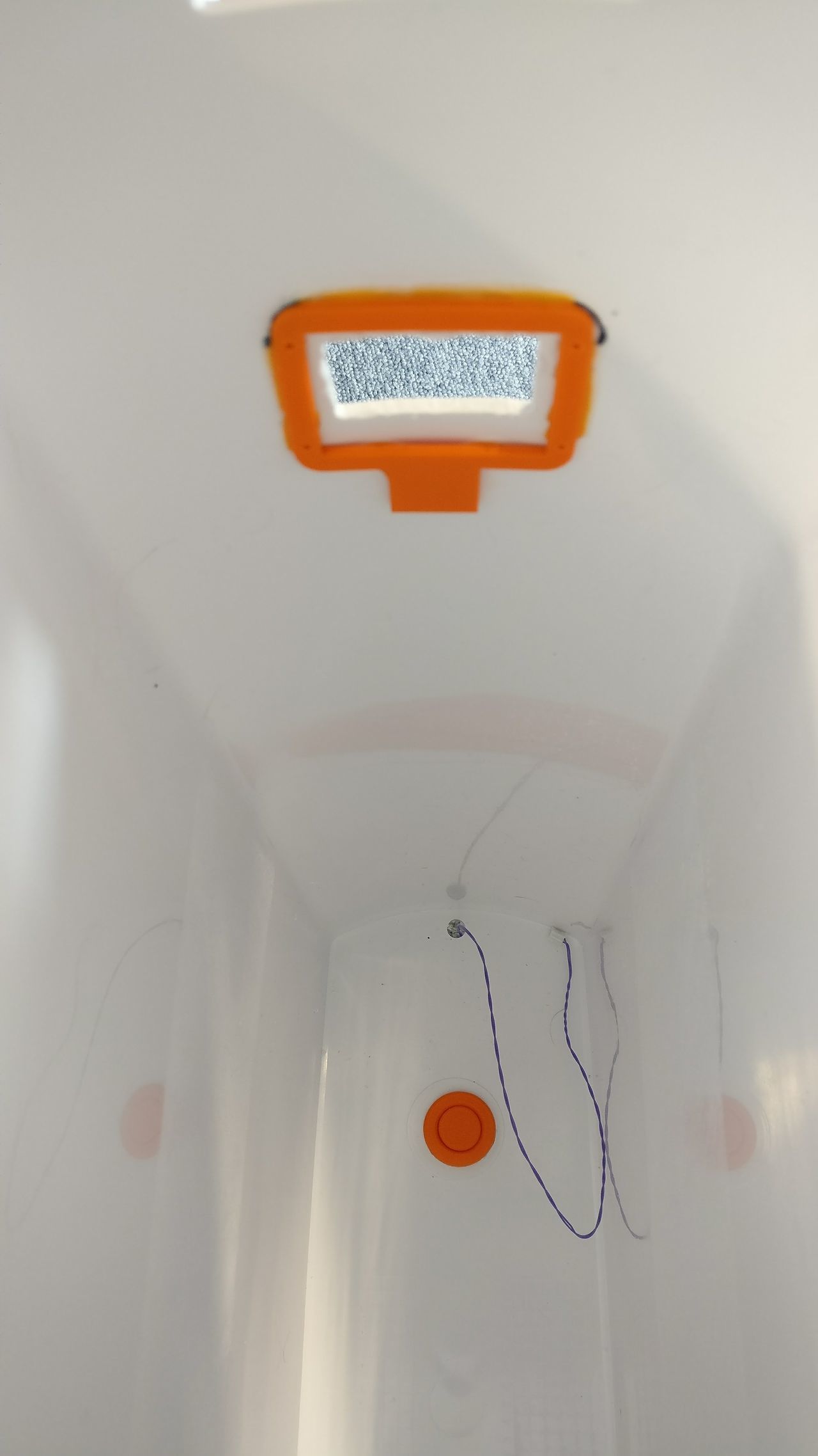
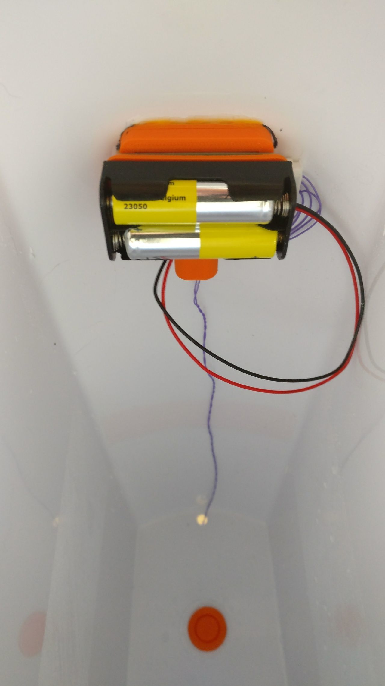
Assembly
To put the screen and the button in the container, I made some holes with my dremel and a file.
In order to have a removable device, I created some 3D printed parts :
- A deck, glued to the container
- The main part, where the screen is screwed on, as well as the third part
- The last part, which is a little plate used to clip the battery holder.
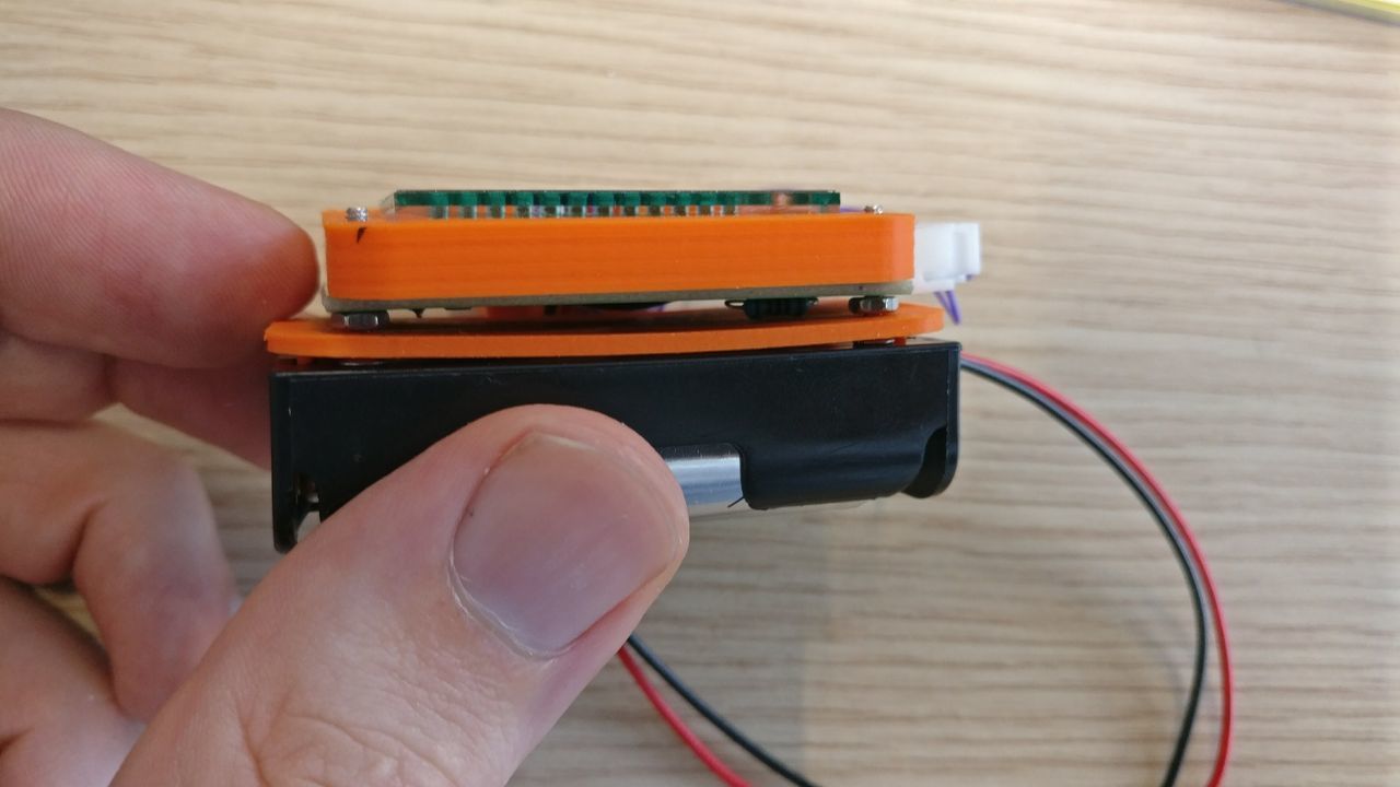

Final result
The device runs around 150µA in power-down mode[1] (with the screen on), so it will run on one pack of batteries for near 700 days.
In fact the screen consumes a lot more current than the ATtiny.
I tried to power the device below 3.3V. It runs quite well around 2V, even if the screen is not as contrasted as at 3.3V. Below, the screen is hard to read.
I can expect at least one year by battery pack !
Update: After more than 200 days, the device is still working fine !

And around 1mA in idle mode ↩︎