DSO138 [1]: Assembly
I acquired a cheap oscilloscope, the DSO138, in kit. The first step is to assemble the pieces!
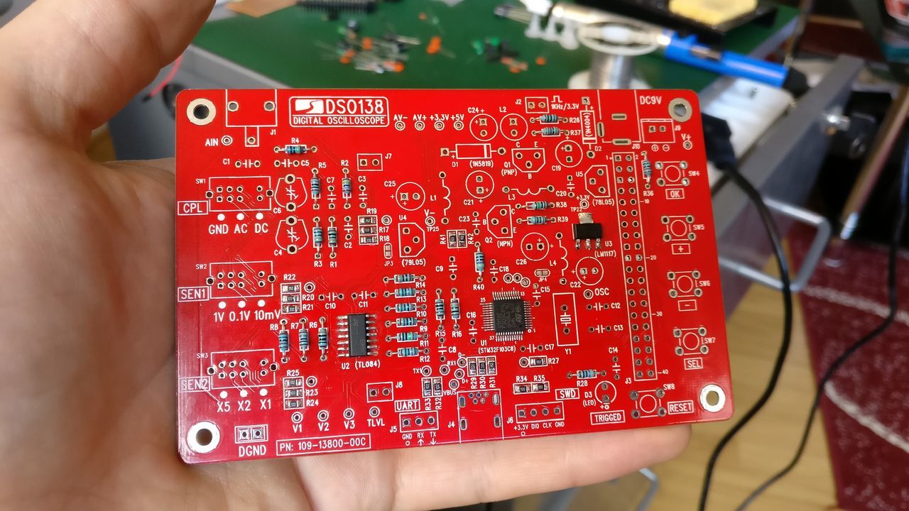
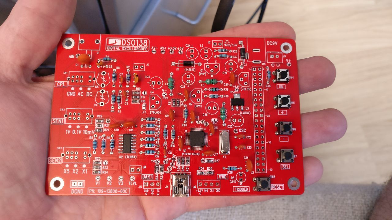
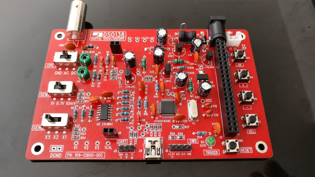
![DSO138 [1]: Assembly](https://storage.ghost.io/c/fe/14/fe1439bb-44cb-4fc0-aa30-44bf49d2ab9f/content/images/size/w2000/2016/08/IMG_20160807_131236-1.jpg)
To test some circuits, and check power supply stability, I bought a cheap oscilloscope named DSO138 (rev 13804K).

This oscilloscope is a DIY Kit: you have to solder each component on the main board.
One comes with all SMD parts pre-soldered (PN: 13803K, replacing 13801K). The other is with only the main IC (the MCU) pre-soldered (PN: 13804K, replacing 13802K) - this is the one I bought.
For both configurations the MCU has been pre-programmed and no re-programming is required.
Major features of DSO138:
- Analog bandwidth: 0 - 200KHz
- Sampling rate: 1Msps max
- Sensitivity: 10mV/Div - 5V/Div
- Sensitivity error: < 5%
- Vertical resolution: 12-bit
- Timebase: 10us/Div - 500s/Div
- Record length: 1024 points
- Built-in 1KHz/3.3V test signal
- Waveform frozen (HOLD) function available
- Save/recall waveform
This first blog post will illustrate the soldering steps, in accordance with the user manual.
User manual
I scanned the documents for you:
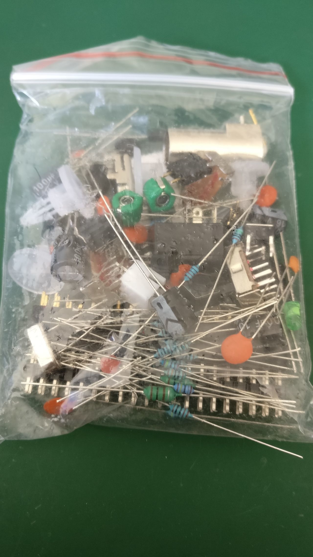
Package content
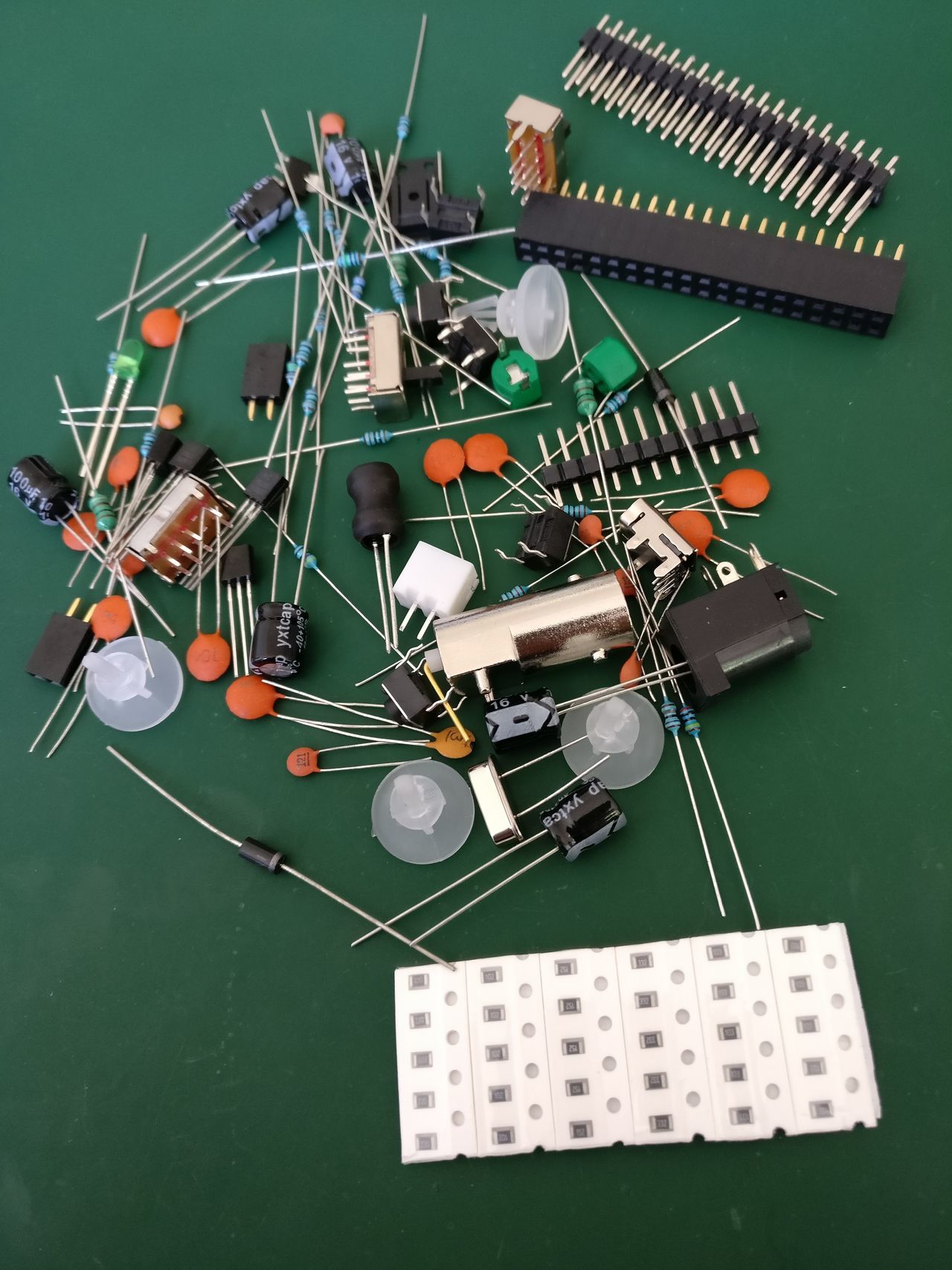
Components
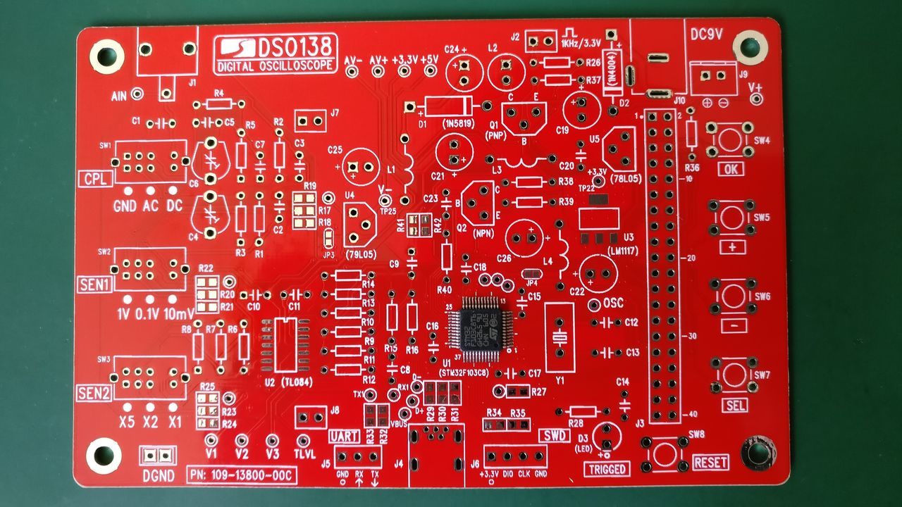
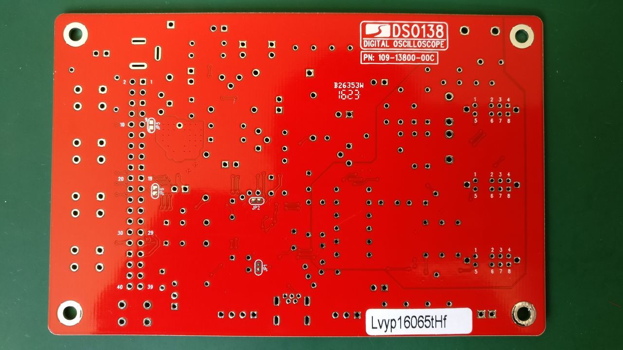
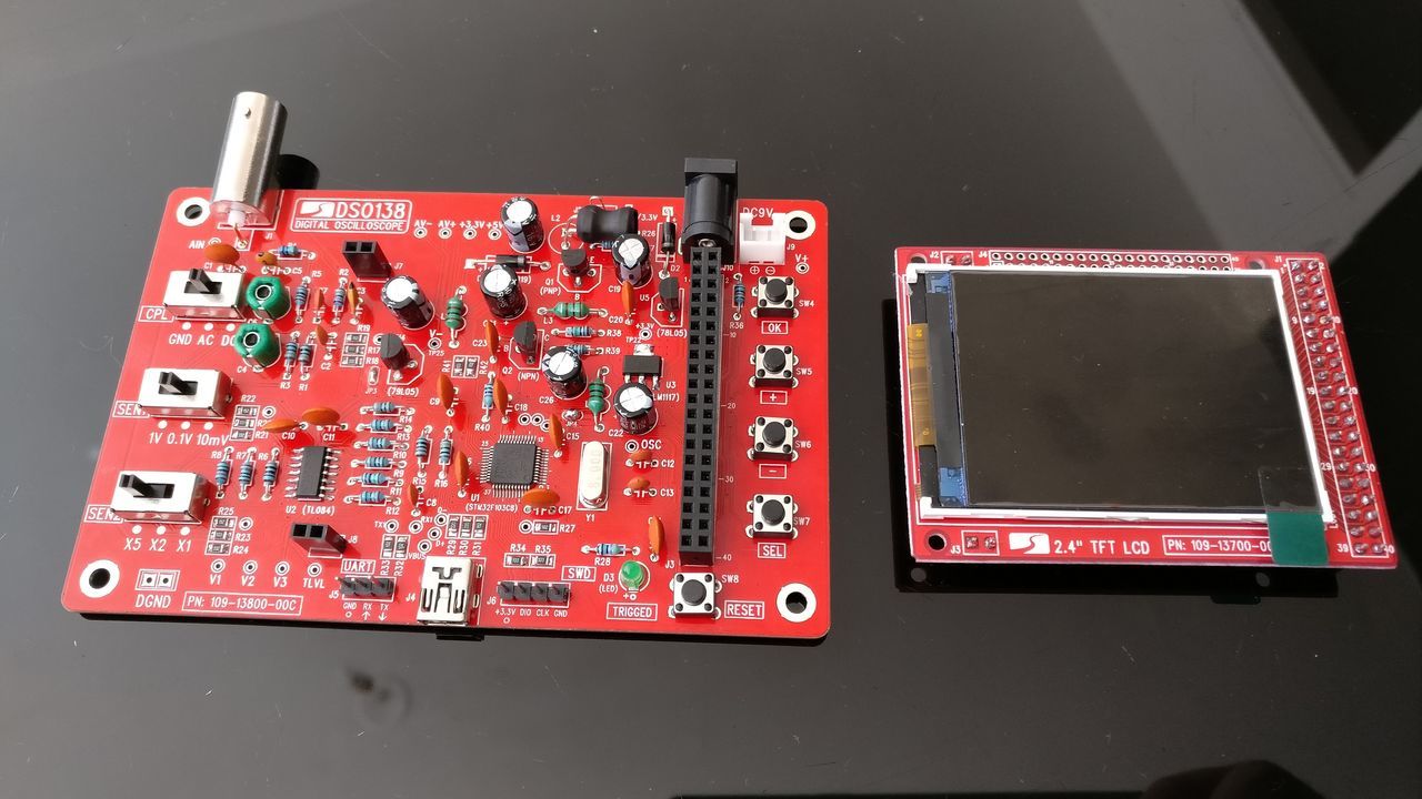
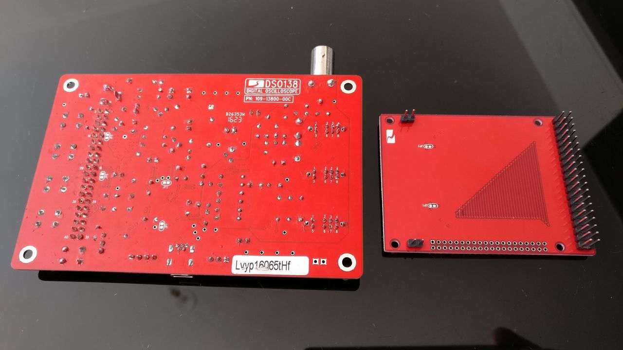
Circuit boards
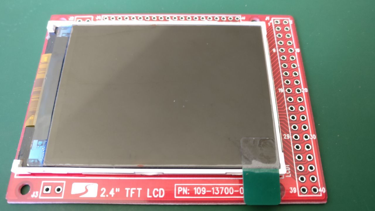
Main board
Screen
Assembly (step by step)
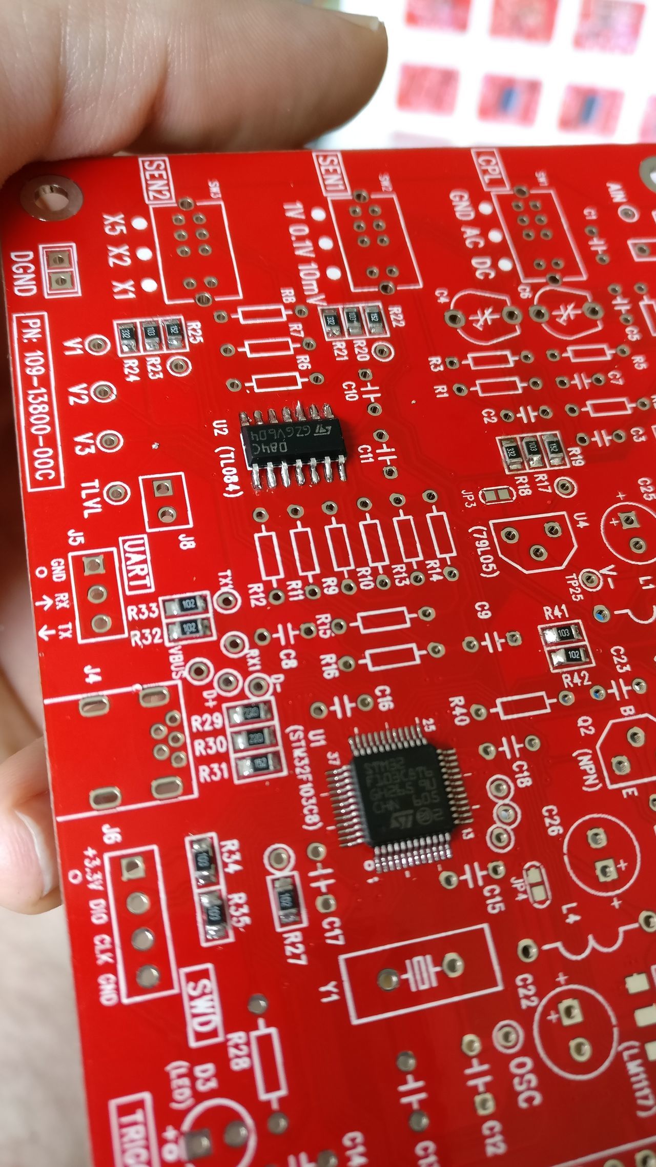
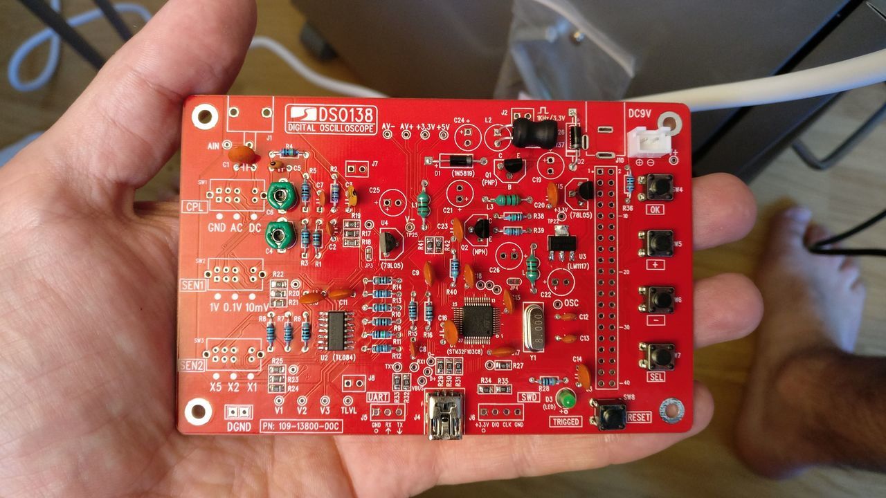
SMT resistors on main board
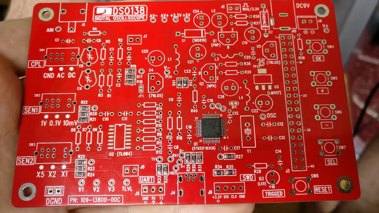
SMT Chip: U2
U3 regulator and Resistors
HF Shokes, diodes and oscillator
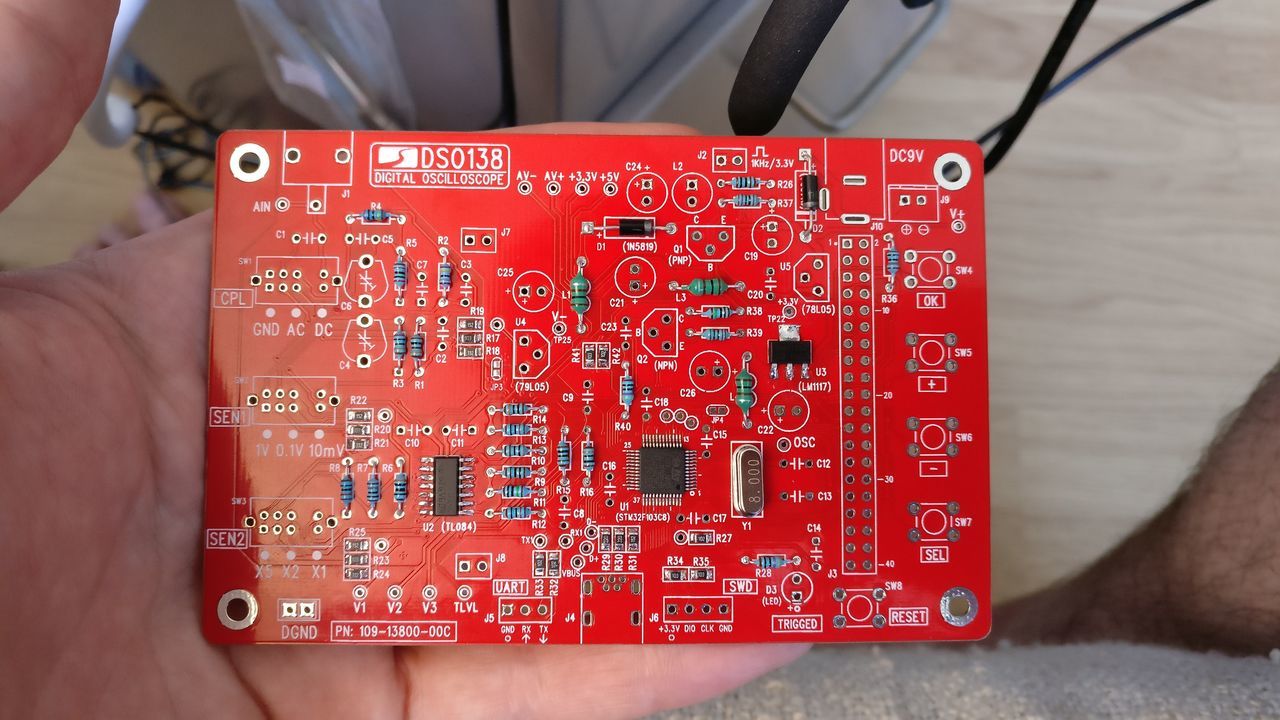
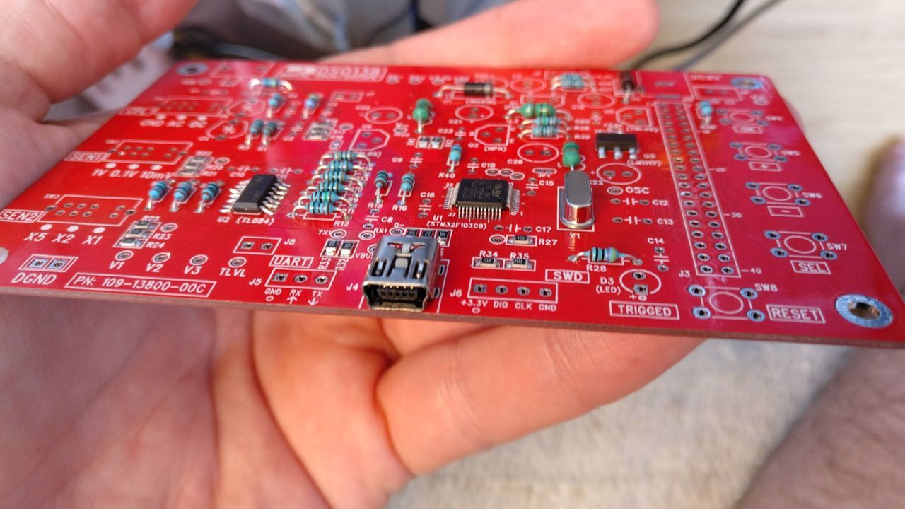
USB Port
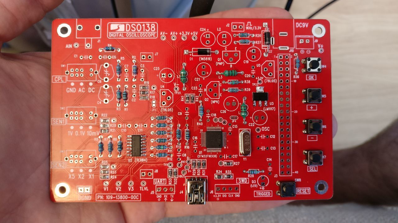
Buttons
Ceramic capacitors
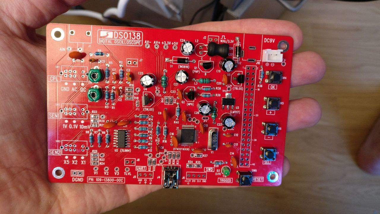
Transistors, Capacitor trimmers, LED, Power inductor, DC socket
Electrolytic capacitors
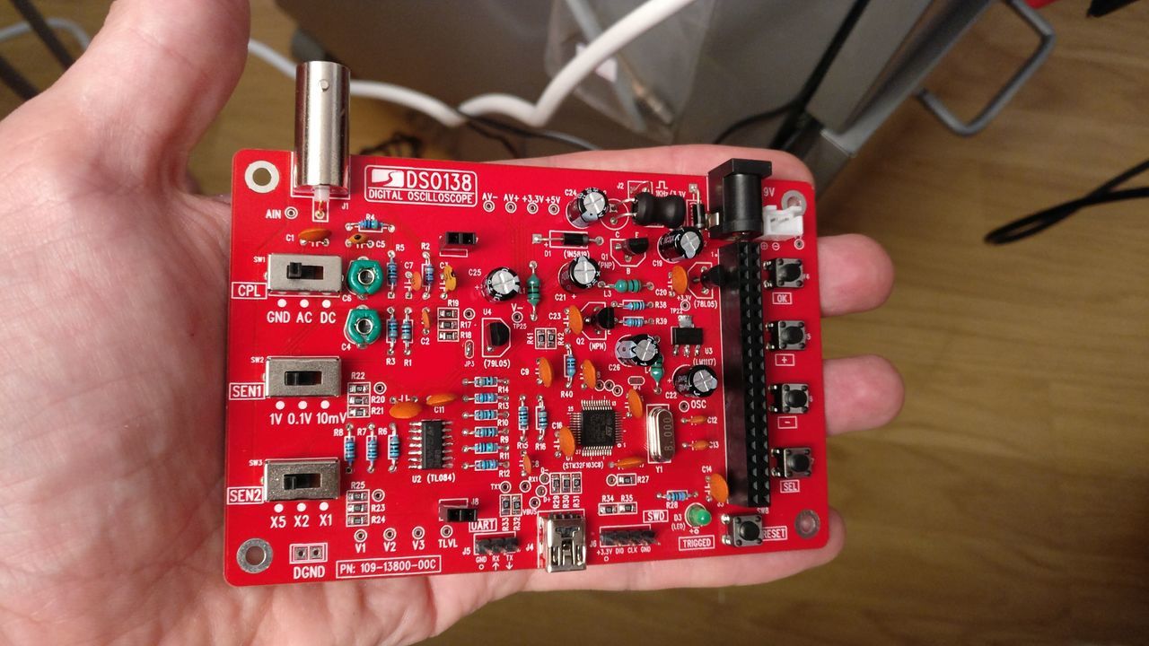
DC Jack, Slide switches, BNC connector, pin headers
To solder the BNC connector, heat it long enough
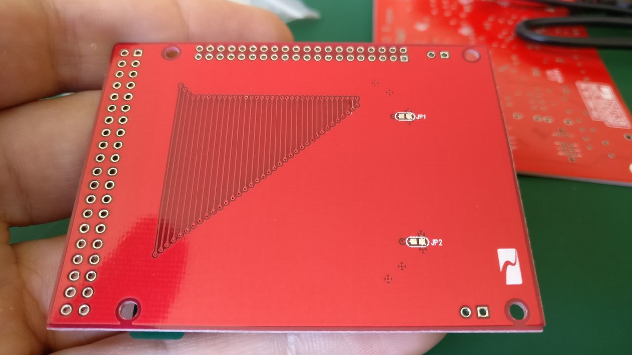
Jumpers
Two jumpers have to be soldered :
- JP3
- JP4 (if the voltage is around +3.3V at TP22)
The other jumpers (JP1, JP2, JP5 and JP6) have to be open for normal running mode.
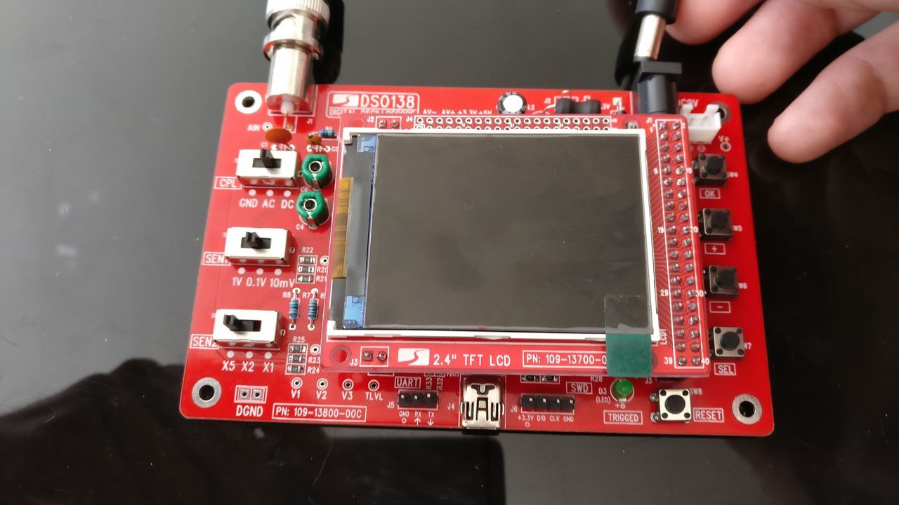
Main board and screen board
Final product
The DSO138 is working fine! I will upload a video in a future post.
Next step
Now that the DSO138 is assembled, I should calibrate the two capacitor trimmers.
After that, I will assemble the plastic box.