Flashing ESP8266 ESP-01
Flashing the ESP8266 in the ESP-01 form is not easy. I built a little circuit to simplify the task.
I recently received my first ESP-01. It was flashed with an old version of Expressif firmware. As I want to use it as an autonomous card, I have to flash another firmware (NodeMCU) on it.
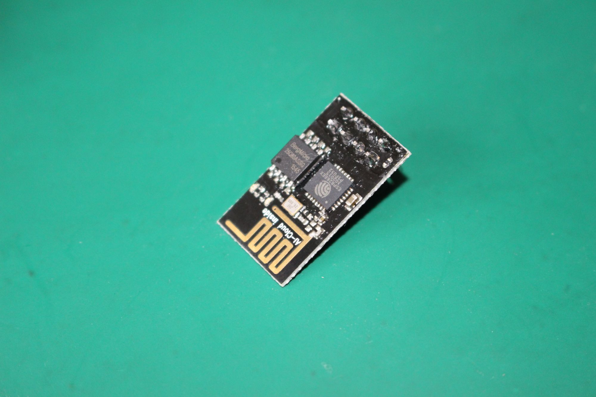
Presentation of the ESP-01
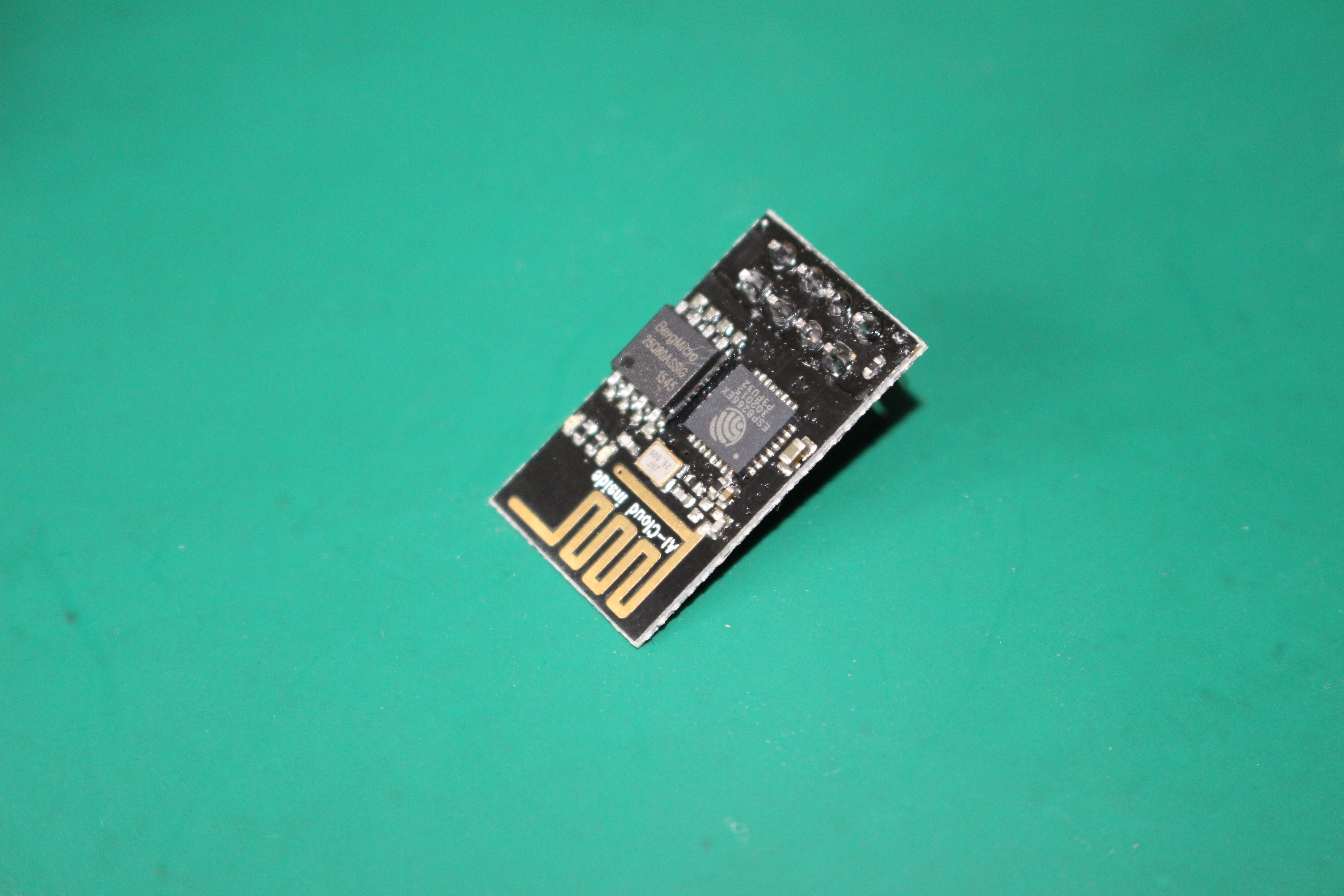
Characteristics:
- 2 dedicated GPIOs
- Serial comms (or 2 additional GPIOs)
- 8 Pins connector
- PWM, I2C, UART
- On-board WiFi + printed antenna, 802.11 b/g/n
- Dimensions: 24.75 x 14.5mm
- Power: 3.3v
Power supply
First, it's important to respect the voltage of 3.3V, for VCC and for RX / TX pins.
One thing I made some time to understand, is that the ESP use a lot of power, during flash mode and Wifi transmission.
In fact, I tried to flash my ESP-01 module many times, and although all seemed to be OK during the flash operation, the card was not working after reboot.
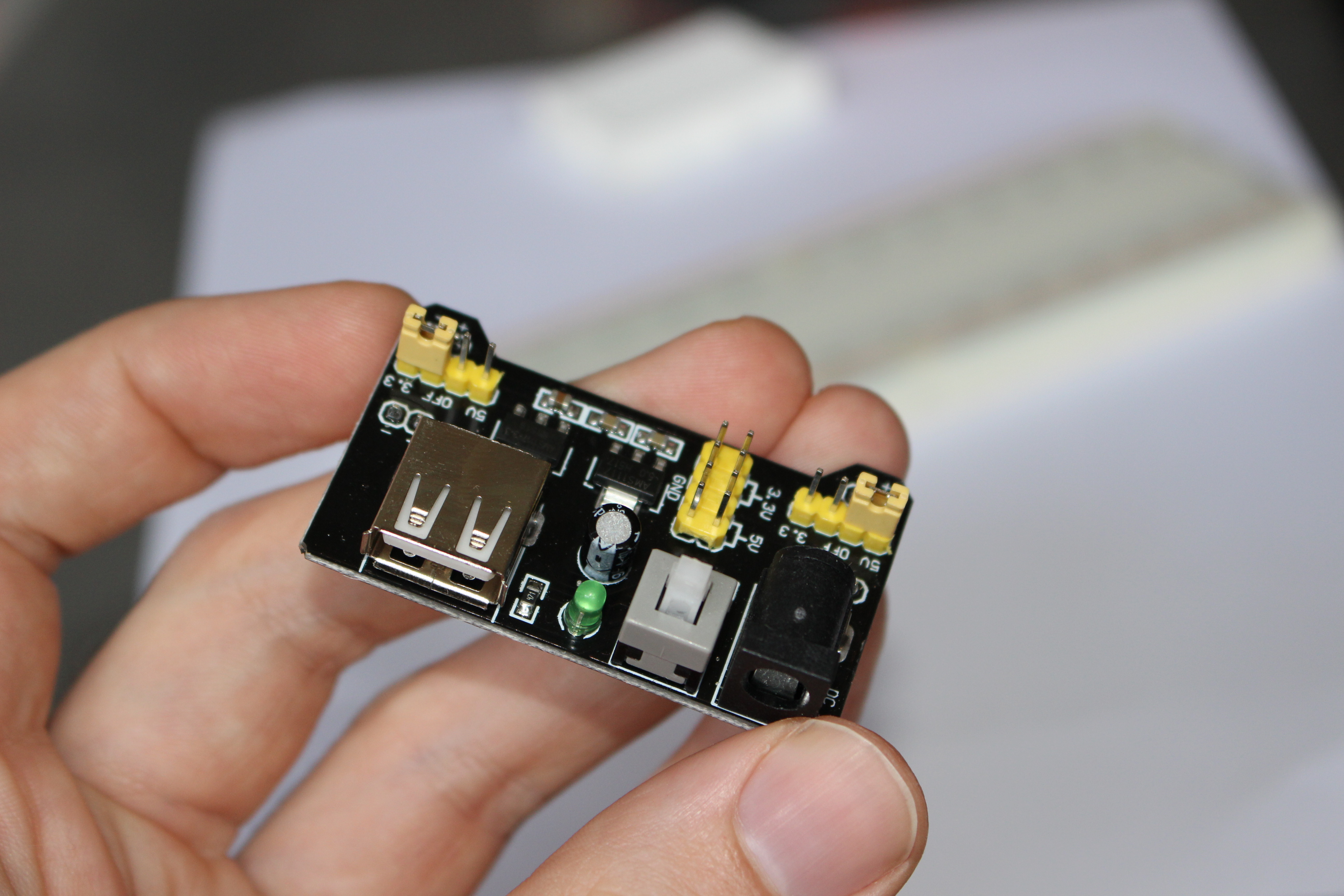
The solution was to use an external power supply. All the following diagrams include such power supply.
I use a breadboard power supply :
Firmware
You can find some informations about NodeMCU firmware on the post about NodeMCU Dev-kit.
The ESP-01 doesn't have a lot of memory, so try to build a firmware with only needed modules.
I used the NodeMCU firmware, on master branch, with file, gpio, net, node, tmr, uart, wifi modules
Flashing circuit
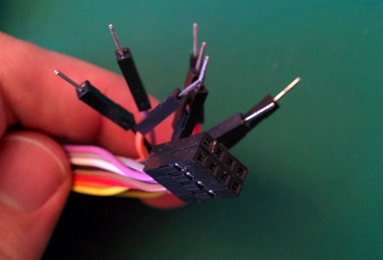
The first problem with the ESP-01, is that you can't plug-it directly on a breadboard (the pin aren't spaced enough).
At first, I made a 8 female pin cable, with dupont cables and some glue.
ESP-01 pins mapping:
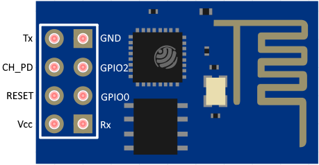
The card, as the other ESP8266 models, has two modes:
- Bootloader mode, for flashing new firmware
- Normal mode, executing the firmware.
The bootloader mode can be launched with a specific configuration during the card reset/power-on:
- CH_PD has to be HIGH
- GPIO0 has to be LOW during boot (can be HIGH once in bootloader mode)
You can provoque a reset of the card by a rising edge on the RESET pin.
Diagram
Below, you will find the diagram circuit for flashing the EPS01, with an external power supply and a USB-Serial converter.
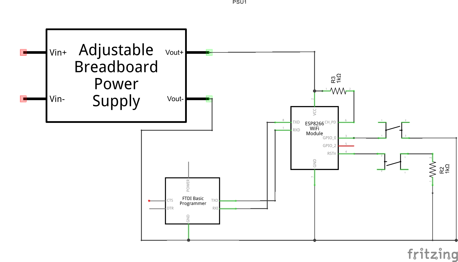
Remarks:
- the resistors are optional
- You have to be sure that the USB/RS converter is using 3.3V levels (some of them have a switch to be on 3.3V / 5V)
On breadboard
On a breadboard. Sadly, I did't take any picture of my real breadboard.
I used the glued dupont cable made before.
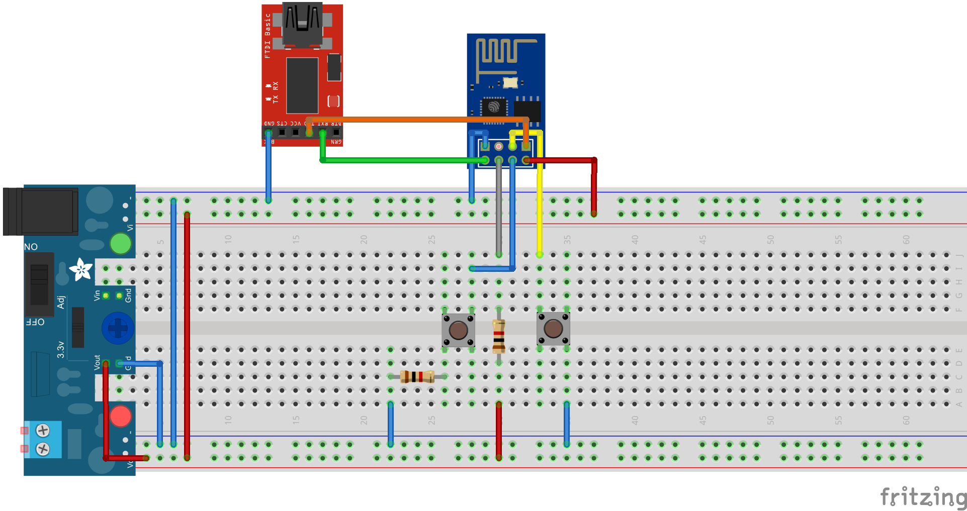
Note that if you don't have push buttons, you can plug in / plug out cables. However, this becomes quickly annoying.
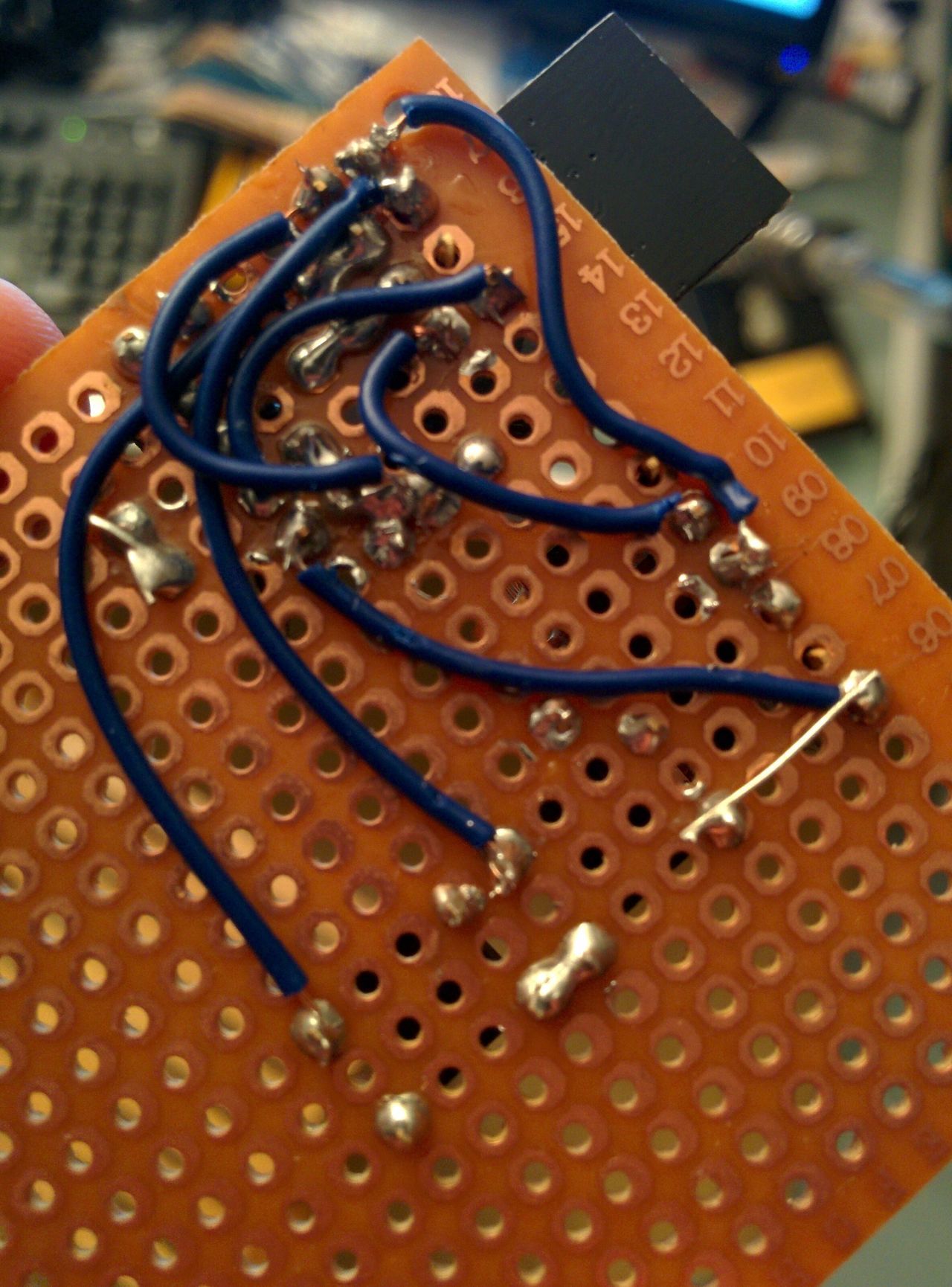
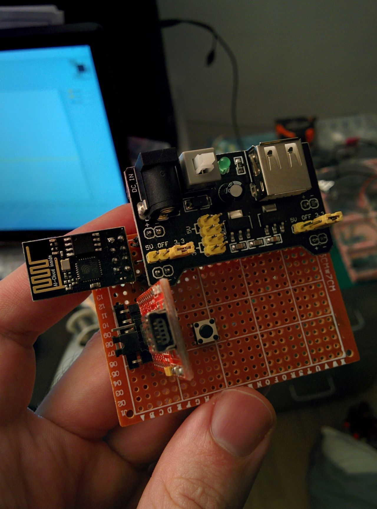
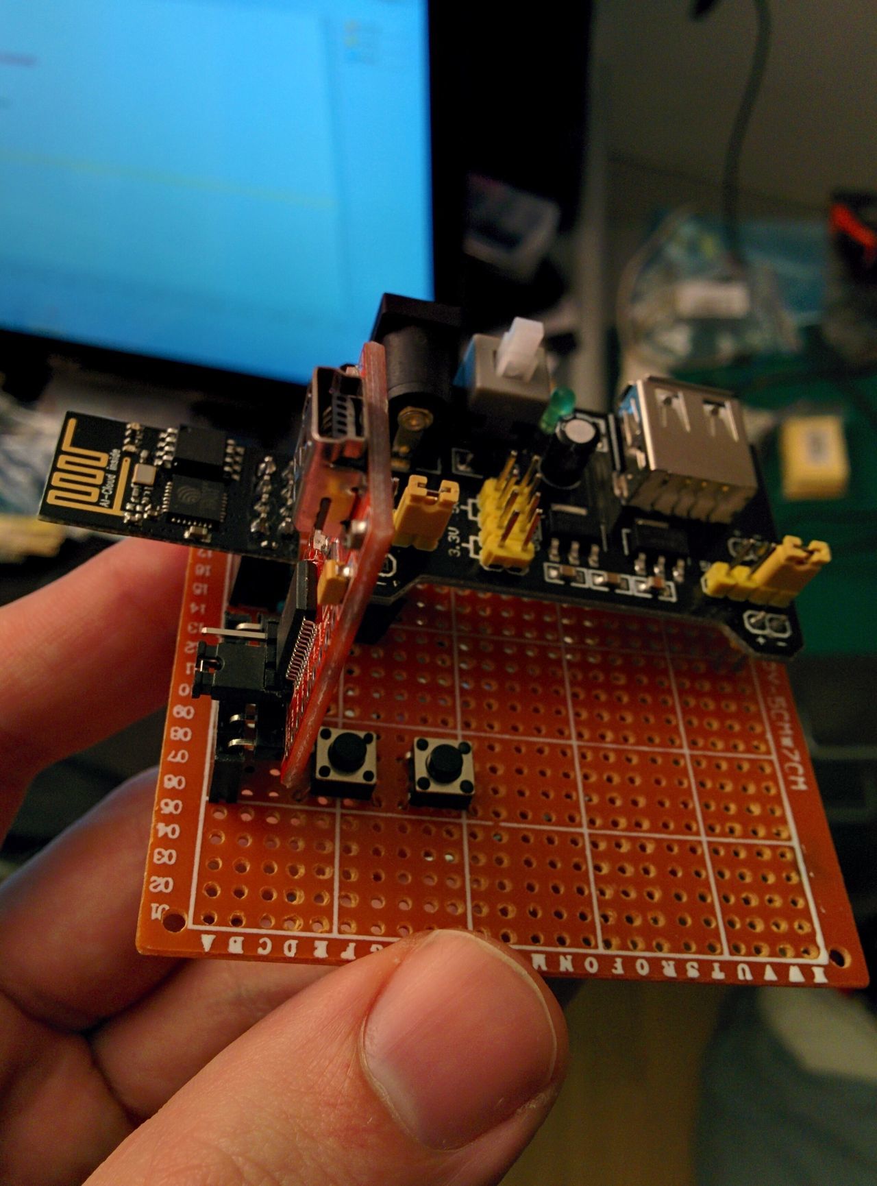
On perfboard
After using the breadboard, I made the simple circuit on a perfboard. It has the advantage to be permanent. I just have to plug the power supply module, the USB/RS converter, and the ESP01.
Time to flash
- Use ESP8266Flasher, binary "ESP8266Flasher.exe"
- In the "Config" tab, select your binary on the first field
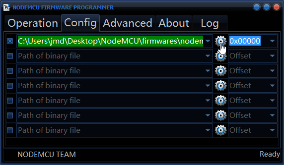
- In the "Operation tab", select the COM Port of your NodeMCU board if necessary
- Push and hold the two buttons of your circuit
- And click the "Flash" button
- Release the "Reset" button; the board starts in bootloader mode
- Wait few seconds before releasing the GPIO0 button
- Wait few seconds (look at the progress bar)... and that's it !
Now, you should be able to connect to your ESP-01 (9600 bauds).
Next step
The next step is to do the same with an EPS-12 module.
For my freezer door sensor, I think will use ESP-12 module, and rather save the ESP01 for an Arduino setup.