LED pulse with NE555
The NE555 timer is quite cheap and using it is quite different than the usual micro-controllers. Pulsing a LED is a good way to begin with.
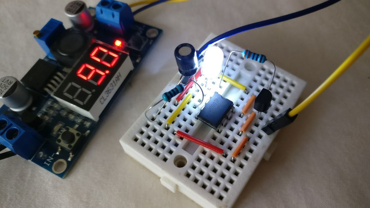
I'm want to create a LED pulse with a simple circuit.
I choose to use a NE555. I found a lot of schematics on the Internet, but often without any explanation, and I don't like to create a cricuit without understanding it.
The NE555 is a very cheap, popular and useful precision timing device that can act as either a simple timer to generate single pulses or long time delays or as an oscillator.
It works at 9V.
Most of the time, to blink a LED, the NE555 is operated as an astable multivibrator with two resistors, one capacitor and one NPN. The timing is adjusted by changing the value of the resistors and the capacitor.
As I want to pulse a LED, I found on Instrucables another circuit, quite simple but without any explanation.
I was expecting to see the load driven by the NPN on the collector side, but if the load is between VCC and the NPN collector, the NPN will be in saturation mode, and the LED will not pusle.
This circuit is quite different than any other schematics that I found, as the pin 2 is directly linked to the pin 6.
Moreover, the output is followed by a RC filter.
NE555 highlights
To understand the behavior of this circuit, it's interesting to look at the simplified schematics of the NE555.
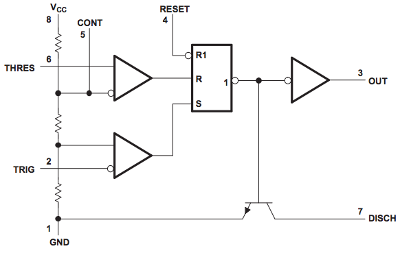
And look at the following pins (with CONT at 2/3 VCC):
- THRES / pin 2 (input): Start of timing input. TRIG < 1/2 CONT sets output high and discharge open
- TRIG / pin 6 (input): End of timing input. THRES > CONT sets output low and discharge low
- OUT / pin 3 (output): High current timer output signal
RC Filter
And a quick reminder on RC filters.
Series circuit (as used in the LED pulse circuit):

Capacitor voltage (Vc) when Vin is set:
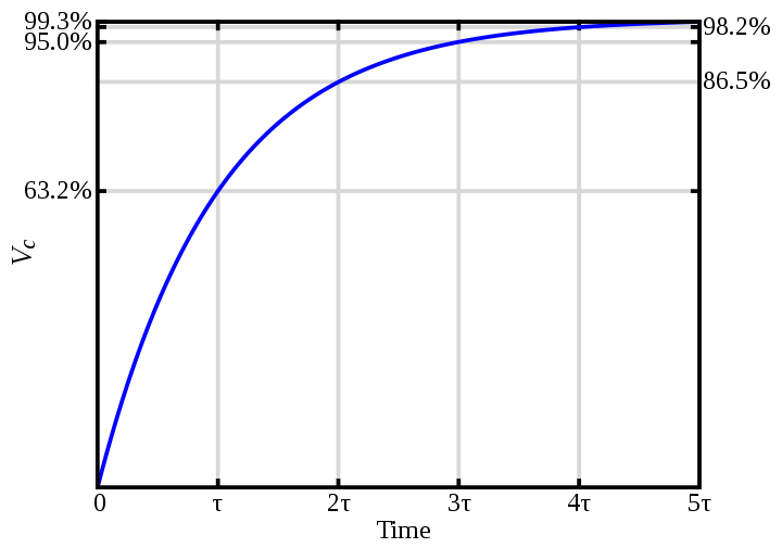
With
τ = RC
NPN in active mode
On the following schematics, we have:
UR + UC = VCC
iR = iC + ib
When UC increases, iC decreases, and when the capacitor is fully charged, iB is almost equal to iR.
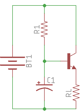
To be able to manage the current flow through the LED, the NPN in used in active mode.
That's why the LED and the resistor are placed after the emitter, and the collector is directly linked to VCC.
Therefore:
VC > VB > VE
In active mode:
iC = βiB
iC = αiE
α = β / (β + 1)
and β is at least 35 for the 2N2222
I want around 16mA in my LED at peak.
iC = βiB with β = 35
iB = 16 * 10-3 / 35 ≈ 0.5mA
So R = VR / iR
R = (2/3 * VCC) / iR = (2/3 * 9) / (0.5 * 10-3) = 12kΩ
With τ = RC, and I want τ = 1s
So C = 1 / R = 83µF
After the maths, I played with a real circuit and decided to use
R = 10kΩ
C = 100µF
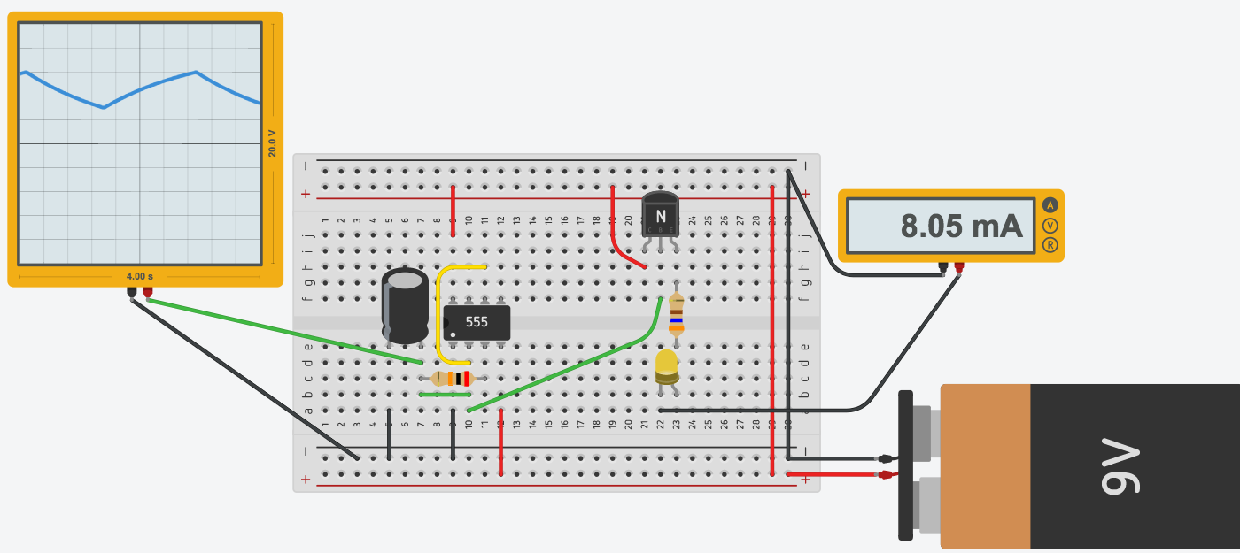
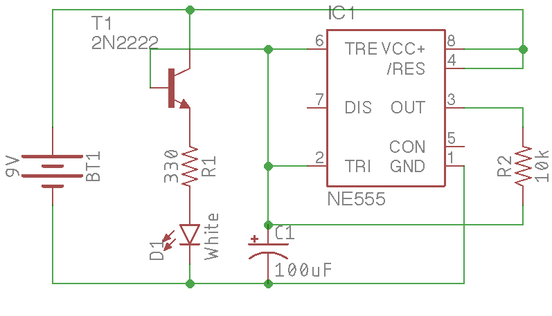
Combining the three circuits
So:
- When the pin 2 is below 1/3 Vcc, pin 3 will be set at HIGH.
- The capacitor will charge at 2/3 Vcc in approximately τ seconds
- The pin 6 will be above 2/3 Vcc and set pin 3 at LOW
- The capacitor voltage will slowly go aroung 1/3 Vcc and the loop begins !
Remark: Output will never be higher than 2/3 Vcc, and lower than 1/3 Vcc (except at the power-up). The resistor and the capacitor will define the time needed to goes up to 2/3 Vcc and down to 1/3 Vcc.
The current flowing to the base is limited by the resistor.
The current flowing into the LED is limited by another resistor.
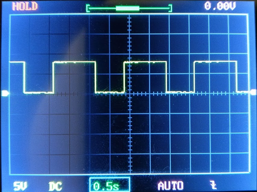
I tried to probe the results with my cheap DSO138.
Please note that my DSO doesn't seems to be well calibrated on ground
Output (pin 3) voltage
We can see the LOW / HIGH change.
The output in LOW level (0V) is shorter than in HIGH level (9V) as it's quicker to discharge the capacitor from 2/3 Vcc to 1 / 3 Vcc than charge it.
Capacitor voltage
We can see that the capacitor charges and discharges between 1/3 Vcc (3V) to 2/3 Vcc (6V).
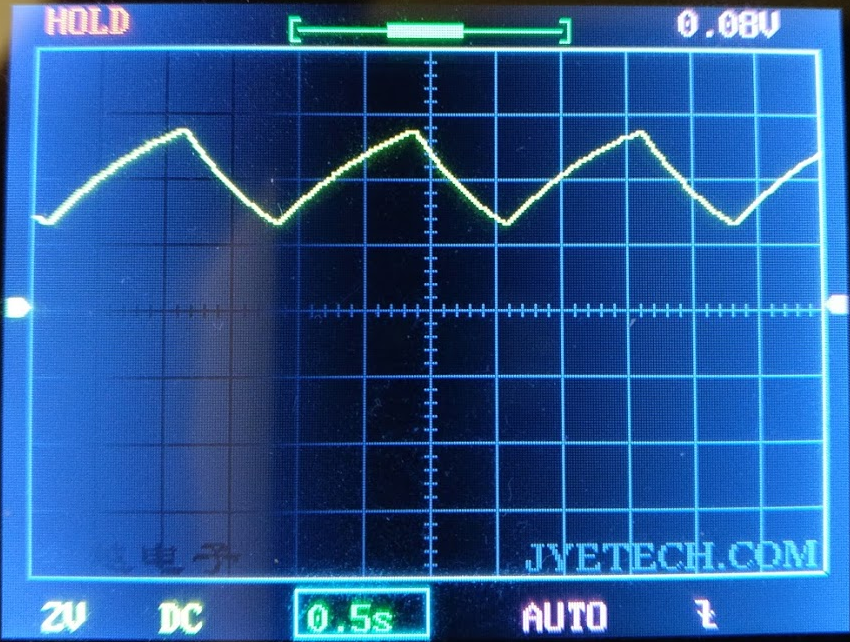
I don't know if we have to take into account VBE which should be around 0.7V when NPN is in saturation mode.
Limit the current through the resistor
Now than the LED is ready to get powered, it's time to compute the second resistor value:
VLED = 3.2V
VR = 9 - 3.2 = 5.8V
R = VR / iR = 5.8 / (16 * 10^-3) ≈ 360Ω
As I don't have any 360Ω resistor, I will use a 330Ω resistor.
Final schematics
Result in video
Next step: I want to include this montage into a Tardis, but only power up the circuit when there is some lights in the room (the Tardis will be put in a bathroom whithout any window).