NPN transitor in application
How to use NPN to control large current which an output pin of an Arduino board cannot manage by itself

I received some NPN transistors (2N2222). I hope to use them to power on / off some sensors, requiring too much energy to be supplied by the Arduino card (next step!).
But before doing that, I need to understand how use them.
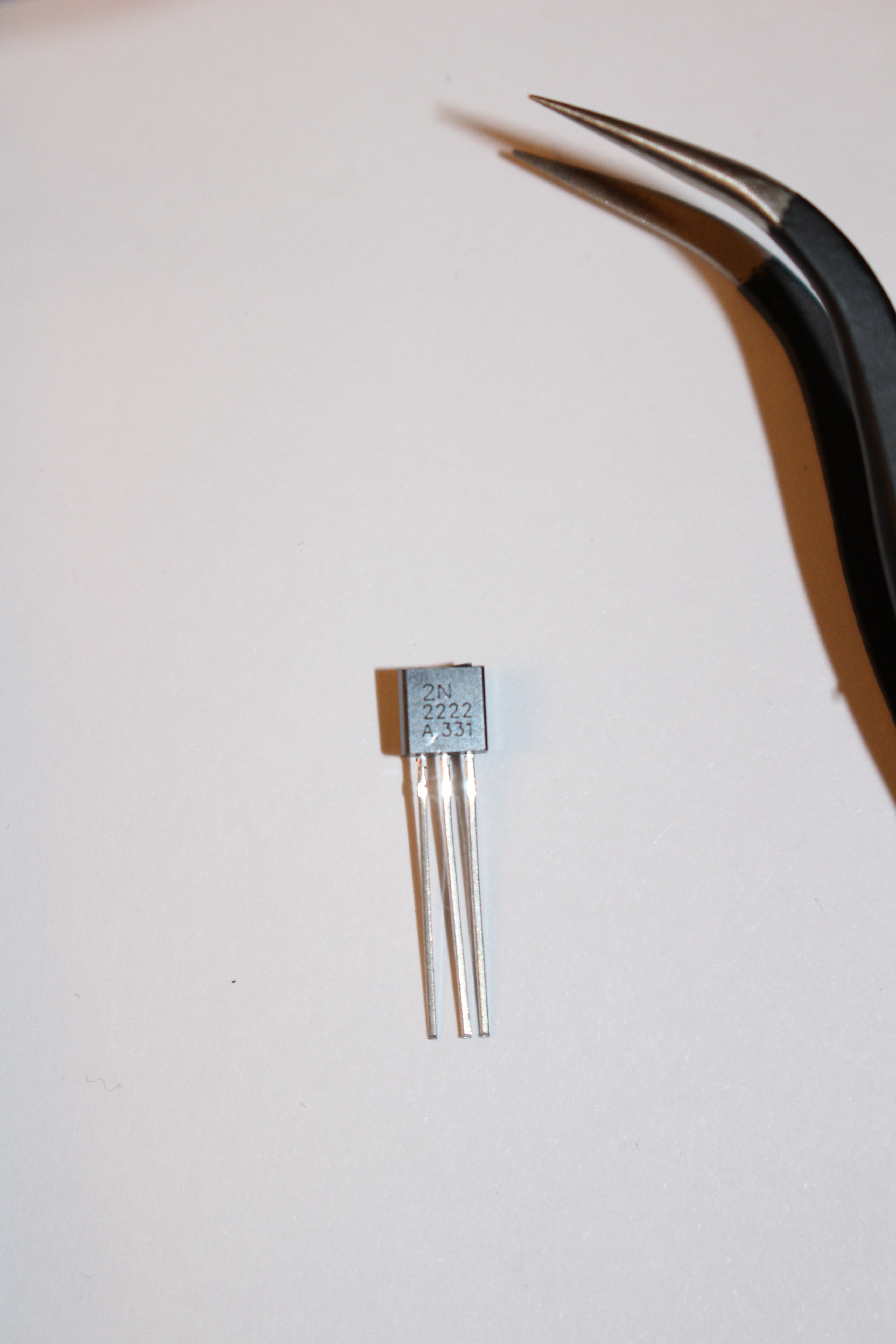
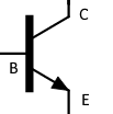
These bugs have 3 pins:
- Collector
- Base
- Emitter
I understood that they can be used to let current pass or block it.
Even better, the power source to switch off / switch on the transistor as not to be the same as the one controlled.
By the way, this french video is great to understand how the BJT transistors work: https://www.youtube.com/watch?v=Zud1Y9S7Jd0
The four transistor operation modes are:
- Saturation – The transistor acts like a short circuit. Current freely flows from collector to emitter.
- Cut-off – The transistor acts like an open circuit. No current flows from collector to emitter.
- Active – The current from collector to emitter is proportional to the current flowing into the base.
- Reverse-Active – Like active mode, the current is proportional to the base current, but it flows in reverse. Current flows from emitter to collector (not, exactly, the purpose transistors were designed for).
Today, I want to do something simple, and just use it in saturation mode and cut-off mode.
The current passing through the collector (IC) is linked to the current passing through the base (IB), knowing that IC >> IB
Each NPN transistor have a "current gain", noted hFE or β.
hFE varies with temperature and even between transistors of the same sort
hFE min/max can be found in the datasheet of the transistor, and some multimeters are able to mesure it.
hFE links IC and IB with the following equation:
IC = hFE * IB
And
IE = IB + IC
I use my multimeter to check the value of the one I want to use for my circuit.
After doing my circuit, I learned that it is a bad practice. In reality, you have to look in your datasheet, and take the lowest value of hFE for your calculation.
Another thing good to know :
For silicon transistors VBE ≅ 0.7V
I made a little circuit to use my NPN transistor:
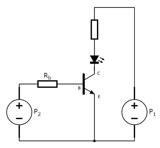
Saturation mode
How compute RB to be in saturation mode ?
Please note that in reality, I used the same power source for P1 and P2
VP1 = VP2 = 5V
For my transistor:
35 < hFE < 300
Here, I want to have
Ic = 18mA
So the sub-question is :
Which current have to pass through IB to be in saturation mode ?
As I'm dumb, and I use the real value of hFE for my transistor (instead of hFE_min)
hFE = 290 (should be hFE = 35)
IC = 18mA = hFE * IB
IB = IC / hFE = 18 * 10-3 / 290 = 62µA
Now, we can compute the value of VR :
VR = VP2 - VBE = 5V - 0.7V = 4.3V
And finally, the value of RB!
RB = VR / IB = 4.3 / (62 * 10-6) = 69kΩ
As I don't have a 69kΩ resistor, I will use a 64kΩ resistor.
I didn't know when I made my circuit, but it's better to multiply IB by a factor of 1.5 to be sure that the transistor will be in saturation mode.
IBsat = IB * 1.5 = 93µA
RB = VR / IBsat = 4.3 / (93 * 10-6) = 46kΩ
Cut-off mode
It's way easier :)
As we saw earlier :
IC = hFE * IB
So,
If IB = 0, IC = 0
To be in cut-off mode, you just have to turn off the power supply
VP2 = 0