BLE sensor with the nRF51822 chip
The journey of building a BLE sensor prototype, with a custom firmware based on the Nordic nRF51822 chip and the Ardunio framework.
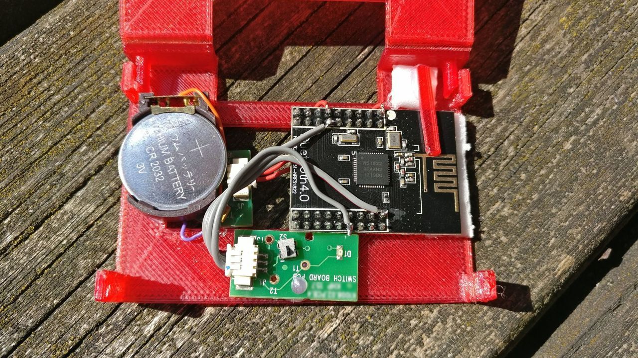
Let's develop a small low power sensor (prototype) which exposes some data over bluetooth, without the help of an other MCU.

I discovered the nRF51822 chip, which is quite old but mainstream, and easily available on AliExpress, and can be programmed.
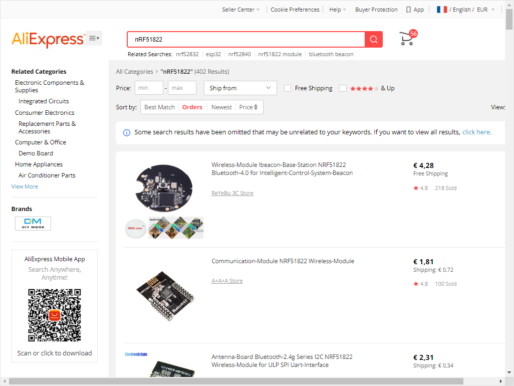
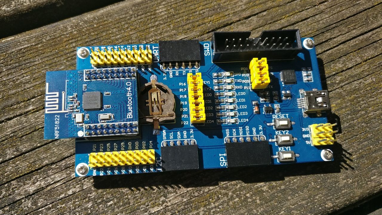
So, I bought a nRF51822 little breakout board, and a development shield name Waveshare BLE400.
I thought it will be easy to use and will allow me to learn to use the mbed os framework. Not as easy as I though... I ended up using the Arduino framework with an easy development environment.
First dive into the chip documentation
I tried to gather a lot of informations about the chip, to understand how to program it.
From the manufacturer website:
The nRF51822 is a general purpose, ultra-low power SoC ideally suited for Bluetooth® Low Energy and 2.4 GHz proprietary wireless applications. It is built around the 32-bit ARM® Cortex™-M0 CPU with 256/128 KB flash and 32/16 KB RAM.
First, the manufacturer website page of the nRF51822 and the datasheet of the BLE400 devboard.
The breakout board of the nRF51822 that I own is a 20 pin board, with a 2mm pitch.
⚠️ It's a 20 pin connector with pin 1 at right - bottom
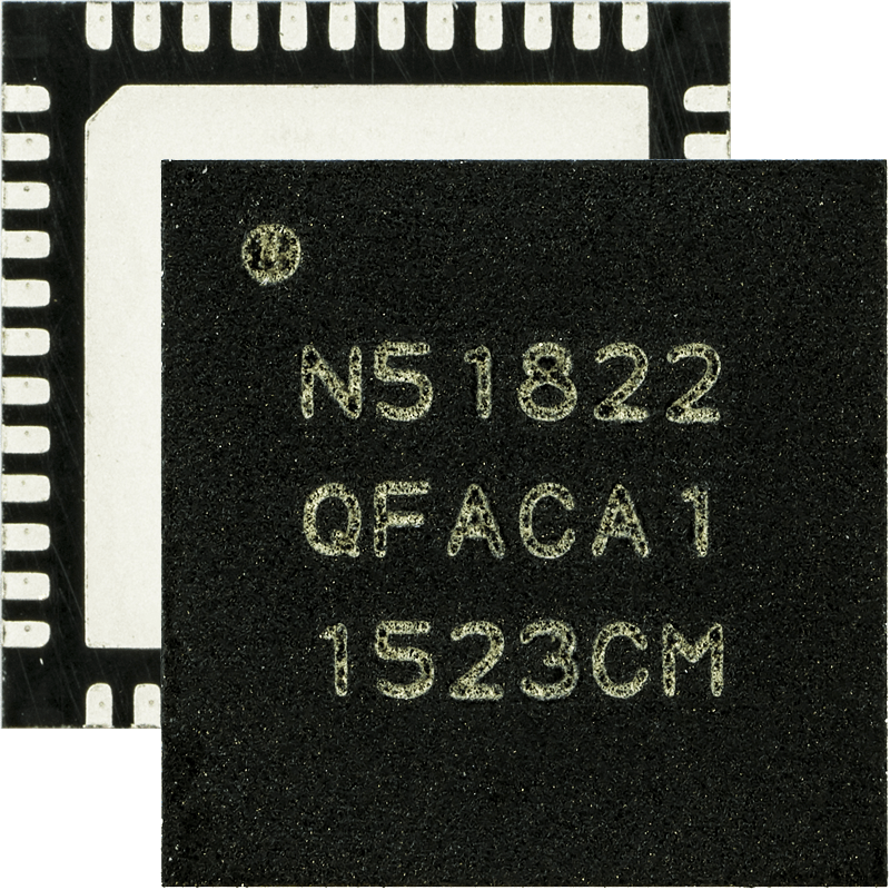
I discovered that the chip exists in different revisions. It's important to note, because the available API differs for each revision.
I personally own revision 3 chips.
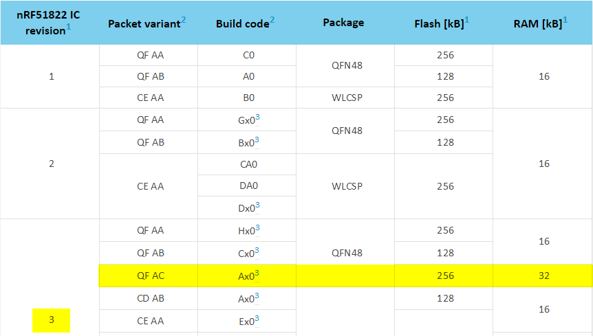
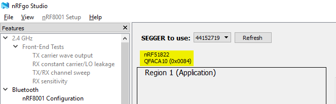
You can check the revision of your chip with the nRFgo studio, and consult the revision matrix afterward.
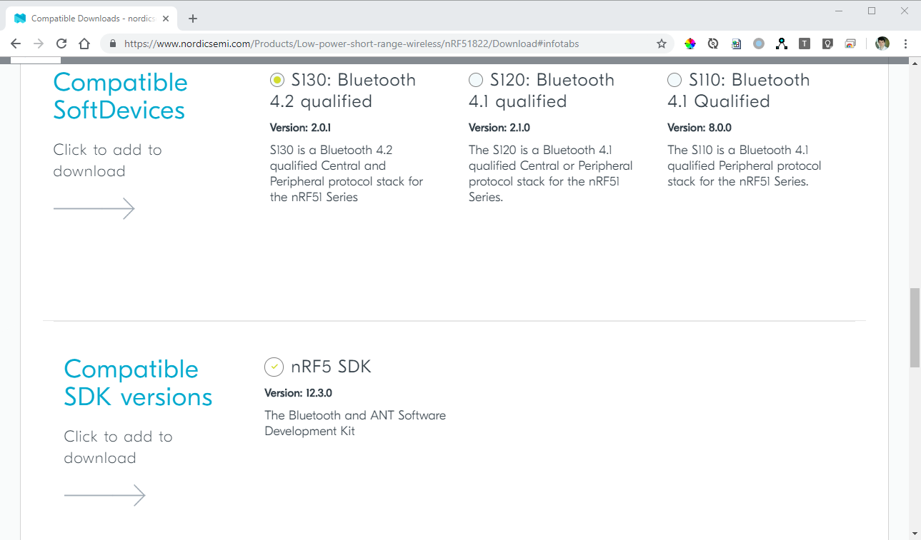
The BLE API are exposed by a Nordic software, side loaded with your software on the chip, named SoftDevice.
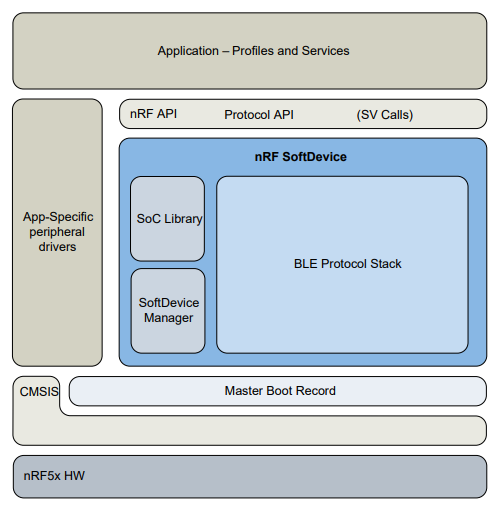
The version of SoftDevice depends on the revision of the chip. See at the SoftDevice Compatibility matrix web page.
Personally, I can use the SoftDevice S130 v2.0.1 with the SDK v12.3.0.
Those binaries are available on Nordic Semiconductor website, as such as the SoftDevice specification.
Focus on the J-Link probe
To flash the nRF51822, Nordic advise to use a J-Link probe. We will try some other (and cheaper) ways later...
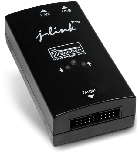
At the time of this article, the latest version is 6.46d. You have to download and install the binaries for Segger website.
The first thing to do is to update you J-Link probe.
- Launch J-Link config tool (JLinkConfig.exe)
- Select the probe
- Click on "Update firmware of the selected emulators"
Be careful, if you have a J-Link probe clone, updating it can brick it.
You can follow this tutorial to erase the serial number of your probe and updating it to the latest firmware release:
Developing and flashing some software the hard way
At first, I tried to use the Nordic development tools.

I downloaded the SDK, the nRFGo studio, a demo of IAR embedded workbench, I bought a J-Link probe... I finally get it working (flashing an SDK example) but I didn't liked the fact the I had to use a complex and expensive IDE.
Sadly, the Segger Embedded Studio, free for Nordic customers, is not compatible with the SDK v12.3.0.
I tried to use PlatformIO as nRF51 development software, with mbed OS. To do so, I choose the Nordic nRF51 Dongle as target. It wasn't possible at the time (I tried the first time in 2017...) to flash it with the J-Link probe out of the box.
I discovered that it's possible to flash the PIO mbed examples (in this case mbed blink example) with the following command lines (and the J-Link probe):
C:\Program Files (x86)\Nordic Semiconductor\nrf5x\bin>nrfjprog.exe --program "platform-nordicnrf51-master\examples\mbed-blink.pioenvs\nrf51_dk\userfirmware.hex" --sectorerase

C:\Program Files (x86)\Nordic Semiconductor\nrf5x\bin>nrfjprog.exe --run
I submitted a PR, allowing me to use the nrfjprog binary from Nordic to flash the chip with PlatformIO.
Please note that you still have to upload the SoftDevice manually with the nRFGo Studio (or more recently with nRF Connect Programmer).
I also asked the mbed community to support the BLE400 development board (without success).
Building a BLE Peripheral with Arduino and PlatformIO
I finally decided that I will use mbed another time, as it's too complicated to create a peripheral, and I found another way.
The nRF51 platform and the Arduino framework are compatible with the BL400 development board.
This specific platform uses the nRF MDK (Microcontroller Development Kit). It enables interactions with Nordic Semiconductor SoCs and SIPs from a 3rd-party IDE.
It means that it's possible to use the Nordic SDK functions in an Arduino sketch loaded on the nRF51822.
To simplify the use of the BLE low-level functions, the BLEPeripheral library exposes some practical functions to create a BLE device, and it's compatible with the nRF51822 chip.
I initialized a new PlatformIO project, and updated the platformio.ini file accordingly:
[env:waveshare_ble400]
platform = nordicnrf51
board = waveshare_ble400
framework = arduino
build_flags = -DNRF51_S130
lib_deps =
  BLEPeripheral
The build_flags parameter defines which version of SoftDevice should be flashed on the device.
You can remove it, but the SoftDevice will not be included and you will not be able to use Bluetooth functionalities.
By default, PlatformIO will use jlink as upload protocol.
I was able to run a Blink example, exposing a service and characteristic, associated to a LED state.
#include <Arduino.h>
#include <SPI.h>
#include <BLEPeripheral.h>

BLEPeripheral blePeripheral = BLEPeripheral();

BLEService ledService = BLEService("19b10000e8f2537e4f6cd104768a1214");
BLECharCharacteristic ledCharacteristic = BLECharCharacteristic("19b10001e8f2537e4f6cd104768a1214", BLERead | BLEWrite);

void setup()
{
  pinMode(PIN_LED1, OUTPUT);

  blePeripheral.setAdvertisedServiceUuid(ledService.uuid());
  blePeripheral.addAttribute(ledService);
  blePeripheral.addAttribute(ledCharacteristic);
  blePeripheral.setLocalName("BLE400 Board");
  blePeripheral.begin();
}

void loop()
{
  BLECentral central = blePeripheral.central();

  if (central)
  {
    while (central.connected())
    {
      if (ledCharacteristic.written())
      {
        if (ledCharacteristic.value())
        {
          digitalWrite(PIN_LED1, HIGH);
        }
        else
        {
          digitalWrite(PIN_LED1, LOW);
        }
      }
    }
  }
}
The device and characteristic can be manipulated with the nRF Connect mobile app from Nordic. I also planned to build a custom mobile app.
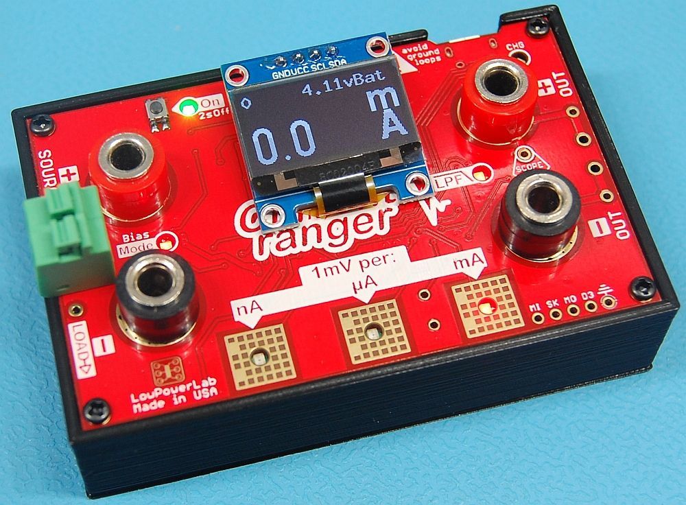
Low power requirement
My sensor has to consume as less power as possible, as I want to power it with a CR2032 batterie. I will test it with the Current Ranger.
So, instead of using the loop function to read / write characteristics, the peripheral code should be event based, and use the low power mode of the chip when no event has to be consumed.
To sleep, the user program should call the sd_app_evt_wait() function:
/**@brief Waits for an application event.
 *
 * An application event is either an application interrupt or a pended interrupt when the
 * interrupt is disabled. When the interrupt is enabled it will be taken immediately since
 * this function will wait in thread mode, then the execution will return in the application's
 * main thread. When an interrupt is disabled and gets pended it will return to the application's
 * thread main. The application must ensure that the pended flag is cleared using
 * ::sd_nvic_ClearPendingIRQ in order to sleep using this function. This is only necessary for
 * disabled interrupts, as the interrupt handler will clear the pending flag automatically for
 * enabled interrupts.
 *
 * In order to wake up from disabled interrupts, the SEVONPEND flag has to be set in the Cortex-M0
 * System Control Register (SCR). @sa CMSIS_SCB
 *
 * @note If an application interrupt has happened since the last time sd_app_evt_wait was
 *       called this function will return immediately and not go to sleep. This is to avoid race
 *       conditions that can occur when a flag is updated in the interrupt handler and processed
 *       in the main loop.
 *
 * @post An application interrupt has happened or a interrupt pending flag is set.
 *
 * @retval ::NRF_SUCCESS
 */
uint32_t sd_app_evt_wait(void);
The interrupt waking the device should be enabled to be automatically cleared.
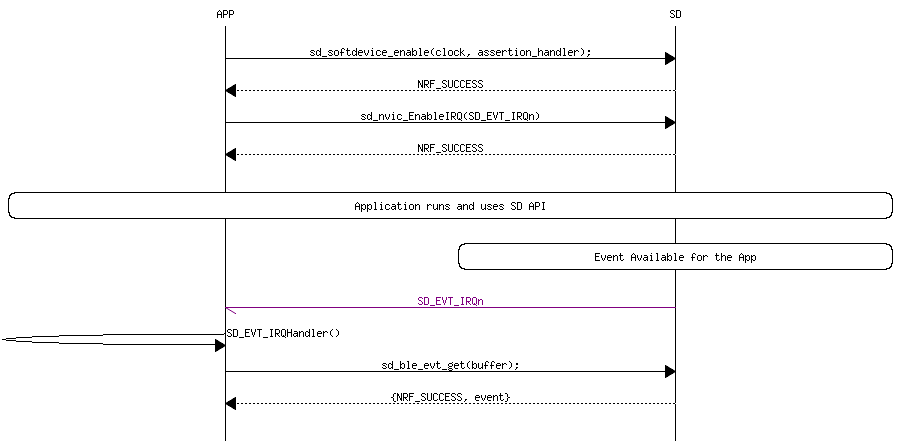
The software interrupt mapping is the following:
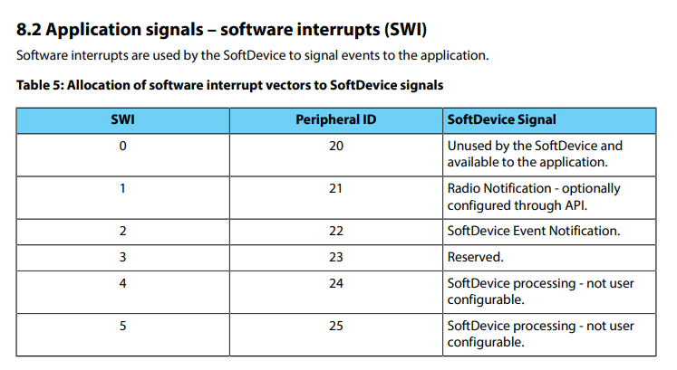
So, to listen SoftDevice event notification, the software interrupt 2 must be turned on. The SWI2_IRQHandler function will be executed for each event (cf. gcc_startup_nrf51.S file content).
I tried to enable the IRQ in the setup(), and add the SWI2_IRQHandler.
Sadly, the nRF seemed to crash instead of calling the IRQ function.
// ⚠️ Not working example

#include "nrf_soc.h"
#include "nrf_nvic.h"

void setup() {
  ...
  blePeripheral.begin();

  // enable low power mode and interrupt
  sd_power_mode_set(NRF_POWER_MODE_LOWPWR);
  sd_nvic_EnableIRQ(SWI2_IRQn);
}

void loop() {
  // Enter Low power mode
  sd_app_evt_wait();
  // Exit Low power mode

  // poll peripheral
  blePeripheral.poll();
}

void SWI2_IRQHandler(void) {
  // NOOP
}
With a lot of failed trials, I decided NOT to enable the IRQ, and manually clear the flag after each wake-up.
I also ended up using a 5 seconds advertising interval to limit the power consumption but still allow the discovery of the device in a suited delay for my application.
The updated code:
#include <Arduino.h>
#include <SPI.h>
#include <BLEPeripheral.h>
#include "nrf_soc.h"
#include "nrf_nvic.h"

#define ADVERTISING_INTERVAL 5000

///
void characteristicWrittenCallback(BLECentral&, BLECharacteristic&);
///

BLEPeripheral blePeripheral = BLEPeripheral();

BLEService ledService = BLEService("19b10000e8f2537e4f6cd104768a1214");
BLECharCharacteristic ledCharacteristic = BLECharCharacteristic("19b10001e8f2537e4f6cd104768a1214", BLERead | BLEWrite);

void setup() {
  pinMode(PIN_LED1, OUTPUT);

  blePeripheral.setAdvertisedServiceUuid(ledService.uuid());
  blePeripheral.addAttribute(ledService);
  blePeripheral.addAttribute(ledCharacteristic);
  blePeripheral.setLocalName("BLE400 Board");

  blePeripheral.setAdvertisingInterval(ADVERTISING_INTERVAL);
  ledCharacteristic.setEventHandler(BLEWritten, characteristicWrittenCallback);

  blePeripheral.begin();

  // enable low power mode without interrupt
  sd_power_mode_set(NRF_POWER_MODE_LOWPWR);
}

void loop() {
  // Enter Low power mode
  sd_app_evt_wait();
  // Exit Low power mode

  // Clear IRQ flag to be able to go to sleep if nothing happens in between
  sd_nvic_ClearPendingIRQ(SWI2_IRQn);

  // poll peripheral
  blePeripheral.poll();
}

void characteristicWrittenCallback(BLECentral& central, BLECharacteristic& characteristic) {
  // central wrote new value to characteristic, update LED
  if (ledCharacteristic.value()) {
    digitalWrite(PIN_LED1, HIGH);
  } else {
    digitalWrite(PIN_LED1, LOW);
  }
}
Sadly, I still get 1mA consumption as soon as the interrupt is attached.
I read that you can change the interrupt mode from IN event to PORT event:
If you use IN event (high_acc = true) on nRF51 you will get around 800-900 uA. This is because the IN event on nRF51 request the HFCLK and 1V2 regulator as seen in the Product Specification part 8.3. If you use PORT event the current draw should be reduced to almost zero. This is done by setting it to false.
On nRF52 this is different. IN event on nRF52 should not result in higher current draw.
Source
And:
Setting up one or more GPIO DETECT signals to generate PORT EVENT, which can be used either as a wakeup source or to give an interrupt, will not lead to an increase of the current consumption. (PS 8.11)
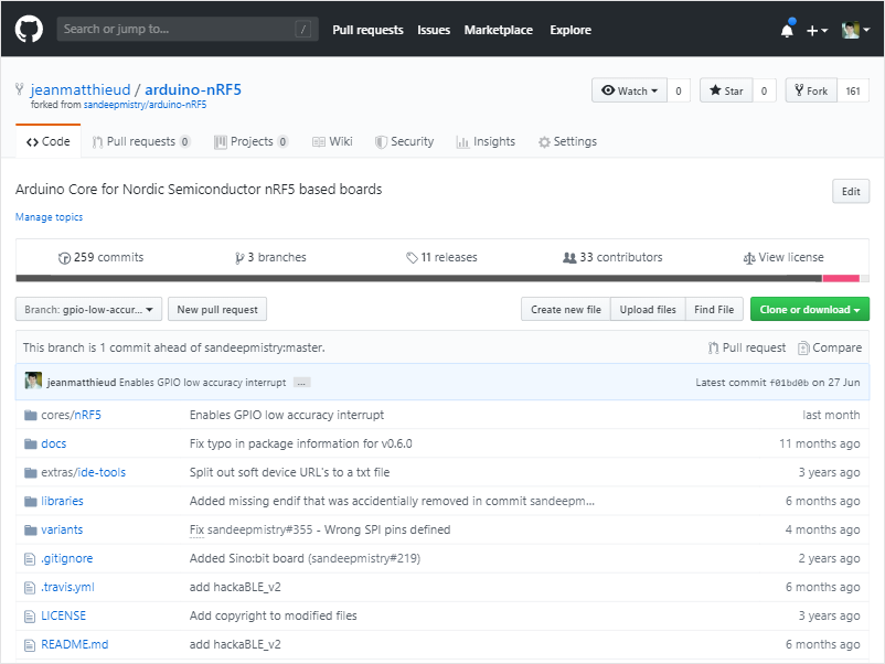
Sadly, the current Arduino platform for nRF5 cannot do that. I created a fork of the platform, to change the behavior of the interrupt vector. I also created a PR, but not currently merged).
With this change, I got a power consumption of 4,8μA in sleep mode (measured with the Current Ranger), which is gives a HUGE battery life (in theory) - more than 5 years with a 220mAh CR2032 cell coin. It important to notice that it doesn't take into account the power consumption during transmission and advertising, but still, it should be enough for my purpose and prototype.
Update advertising scan data
I want to be able to scan the state of a lot of devices quite quickly. Sadly, it's quite slow to discover the devices, connect to the first one, read a value, disconnect, connect to the second device, and so one...
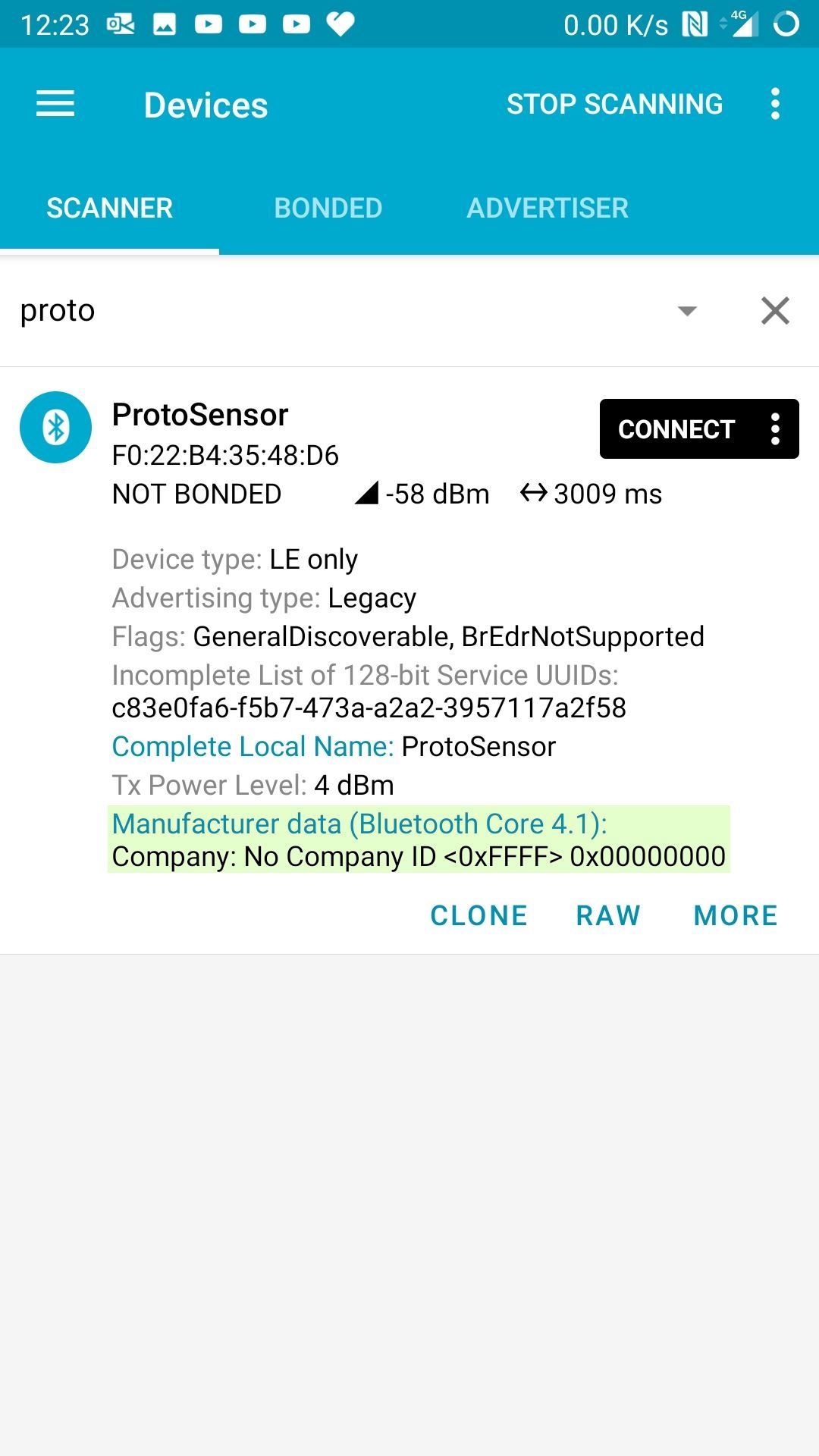
I discovered that the advertising packet can contain some "manufacturer data", aside of the name of the device, the TX power...
The Arduino BLE library updates this packet during the begin() call, and cannot be edited afterwards. I checked the Nordic documentation, and wrote a function calling the Nording API to change it whenever I want:
void updateAdvertisingScanData(const char* localName, uint8_t txPower, uint32_t counterValue)
{
  unsigned char srData[31];
  unsigned char srDataLen = 0;
  int scanDataSize = 3;
  BLEEirData scanData[scanDataSize];

  // - Local name
  scanData[0].length = strlen(localName);
  scanData[0].type = 0x09;
  memcpy(scanData[0].data, localName, scanData[0].length);

  // - Tx Power
  scanData[1].length = 1;
  scanData[1].type = 0x0A;
  scanData[1].data[0] = txPower;

  // - Manufacturer Data
  scanData[2].length = 2 + 4;
  scanData[2].type = 0xFF;
  // Manufacturer ID
  scanData[2].data[0] = 0xFF;
  scanData[2].data[1] = 0xFF;
  // Manufacturer data content
  scanData[2].data[2] = counterValue & 0xFF;
  scanData[2].data[3] = (counterValue >> 8) & 0xFF;
  scanData[2].data[4] = (counterValue >> 16) & 0xFF;
  scanData[2].data[5] = (counterValue >> 24) & 0xFF;

  if (scanDataSize && scanData)
  {
    for (int i = 0; i < scanDataSize; i++)
    {
      srData[srDataLen + 0] = scanData[i].length + 1;
      srData[srDataLen + 1] = scanData[i].type;
      srDataLen += 2;

      memcpy(&srData[srDataLen], scanData[i].data, scanData[i].length);

      srDataLen += scanData[i].length;
    }
  }

  // - Sets only avertising scan data
  sd_ble_gap_adv_data_set(NULL, 0, srData, srDataLen);
}
Thereby, my mobile app can scan the devices around me, and without having to connect to every device, will be able to get the current counterValue of each device.
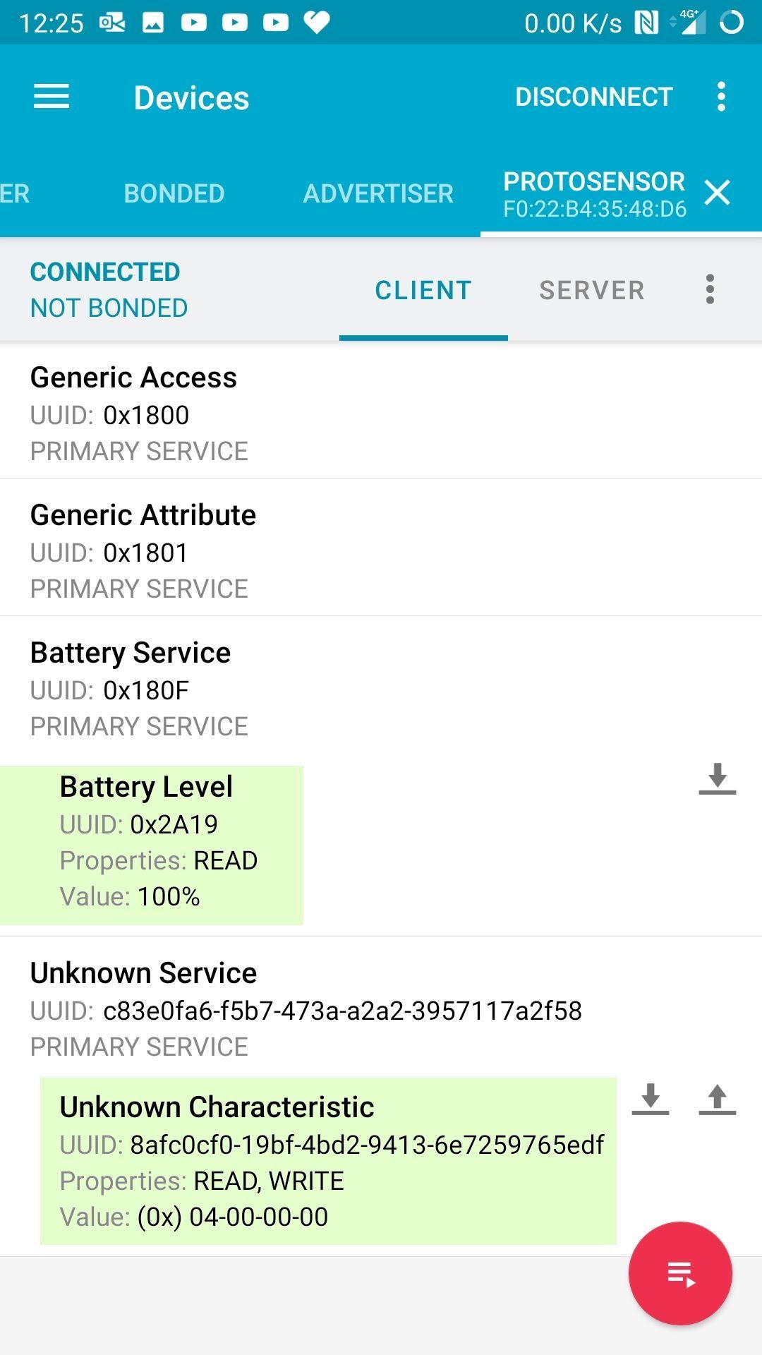
To reset the counterValue, the mobile app will connect to the device and write the corresponding characteristic.
Mobile app
To check the behavior of the sensor, I used nRF Connect for Mobile, available on iOs and Android, before developing my own app with Flutter.

Prototype source code
The full source code can be found on GitHub.
There is a lot of room for improvement to really get a low-power device (e.g. execute code from RAM, use the appropriate power source and voltage regulator...).
You can read the really good nRF51 low power guide and the nRF51 current consumption guide.
Troubleshooting
Flash download error
If you get a similar error while flashing the device:
Downloading file [.pio\build\waveshare_ble400\firmware.hex]...
J-Link: Flash download: Bank 0 @ 0x00000000: 2 ranges affected (2048 bytes)
J-Link: Flash download: Total time needed: 0.098s (Prepare: 0.029s, Compare: 0.021s, Erase: 0.017s, Program: 0.015s, Verify: 0.000s, Restore: 0.014s)
J-Link: Flash download: Restarting flash programming due to program error (possibly skipped erasure of half-way erased sector).
J-Link: Flash download: Skip optimizations disabled for second try.
Error while programming flash: Programming failed.
Try to erase the flash memory:
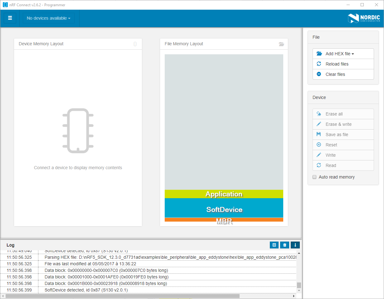
- Start nRF Connect Desktop
- Download and launch nRF Connect Programmer
- Connect to the probe with the "Select device" dropdown menu
- Click on "Device -> Erase All" and disconnect from the probe (with the dropdown menu)
You can now try to flash the nRF51822 again:
Downloading file [.pio\build\waveshare_ble400\firmware.hex]...
J-Link: Flash download: Bank 0 @ 0x00000000: 2 ranges affected (123904 bytes)
J-Link: Flash download: Total time needed: 1.001s (Prepare: 0.027s, Compare: 0.027s, Erase: 0.000s, Program: 0.934s, Verify: 0.009s, Restore: 0.003s)
O.K.
Device reset
When powered by a CR2032 cell, I noticed that the device sometimes resets itself when I try to connect my phone to it.
The input voltage VCC range should be 1.8V to 3.6V (External LDO) or 2.0V to 3.6V (Internal LDO).
Suitable decoupling must be provided by external decoupling circuitry (10uF and 0.1uF). It can reduce the noise from power supply and increase power stability.