Pull-up / Pull-down resistor
Understanding why and how use pull-up and pull-down resistors was mandatory to build my first Arduino based circuit.
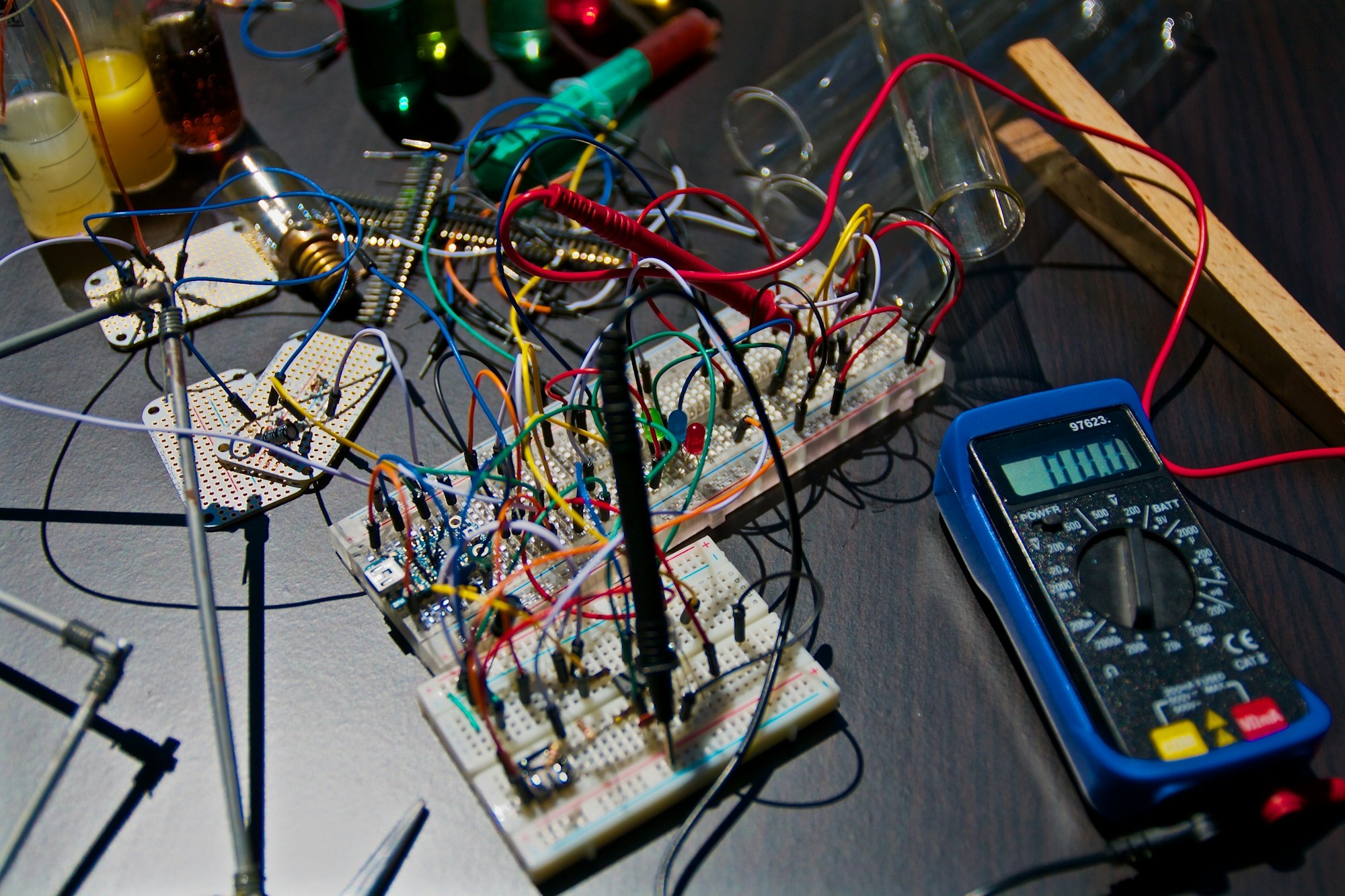
I recently received my first (Chinese) Arduino card.
My first circuit is really simple, read a switch state :)
However, it's not as obvious as it seems (for me :D).
I learned the goal of a pull-up / pull-down resistor.
First attempt
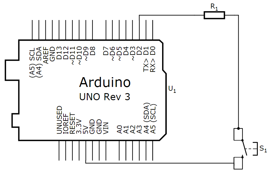
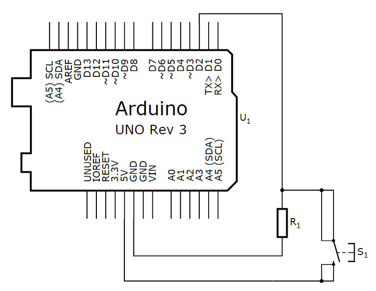
My first attempt : link the Vcc (5V) of my Arduino Uno to a digital input when the button is pressed, detect it by code, and light on the Arduino LED.
Of course, a resistor is needed to control the amount of current passing into the digital input.
It is recommended not to have more than 20mA on a digital input.
Vcc = 5V
Imax = 20mA
Rmin = Vcc / Imax = 250Ω
So, to avoid burning our Arduino card, the minimum value of R is 250Ω. We will use 10kΩ to consume less current (0.5mA instead of 20mA).
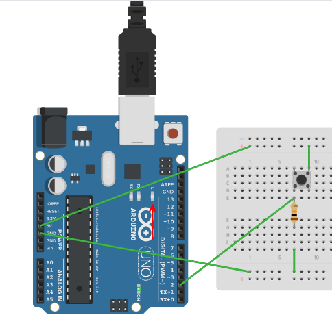
Let's try this :
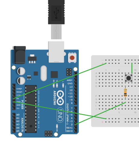
With the following Arduino code :
// Pin 13 has an LED connected on most Arduino boards.
// give it a name:
int LED_PIN = 13;
int SWITCH_PIN = 2;

// the setup routine runs once when you press reset:
void setup() {
  // initialize the digital pin as an output.
  pinMode(LED_PIN, OUTPUT);
  pinMode(SWITCH_PIN, INPUT);
}

// the loop routine runs over and over again forever:
void loop() {
  int switchValue = digitalRead(SWITCH_PIN);
  digitalWrite(LED_PIN, switchValue);   // turn the LED on if the switch input is HIGH
  delay(50);               // wait 50ms
}
Sadly, this doesn't works even in a simulated environnement. In reality, only HIGH level is detected.
The LOW level is not immediate and sometimes not detected at all.
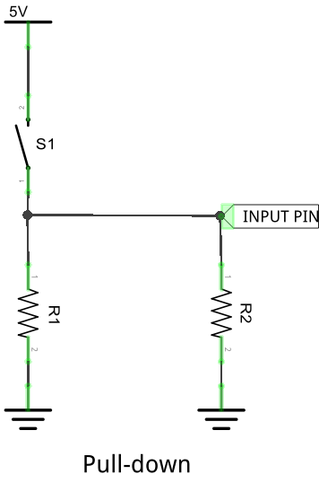
Pull-down resistor
The solution is to add a pull-down resistor.
The principle is simple: when the switch doesn't close the circuit (isn't pressed), a resistor to the ground will close it.
In fact, the Ardunio card use some kind of a resistor to measure the digital input voltage, represented here as R2.
With R2 >> R1
Circuit
Breadboard
Switch released
Switch pressed
Pull-up resistor
Let's note that you can also use a pull-up resistor. In this case, the Arduino will read a HIGH value when the switch is not pressed.
As before, R4 >> R3
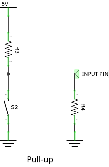
The value of the pull-up resistor needs to be chosen to satisfy two conditions:
- When the button is pressed, the input pin is pulled low. The value of resistor R3 controls how much current you want to flow from VCC, through the button, and then to ground.
- When the button is not pressed, the input pin is pulled high. The value of the pull-up resistor controls the voltage on the input pin.
A low resistor value is called a strong pull-up (more current flows), a high resistor value is called a weak pull-up (less current flows).
We want a R3 value relatively high, to limit the power used when the button is pressed. We also don’t want it too large as to conflict with the second condition.
When the button is not pressed, a very small amount of current flows from VCC through R3 and into the input pin. The pull-up resistor R3 and input pin impedance R4 divides the voltage, and this voltage needs to be high enough for the input pin to read a high state.
R4 >> R3;
so, when button is not pressed, U4 >> U3;
U4 ≈ VCC ≡ HIGH
In order to avoid a custom pull-up resistor, you can use an Arduino internal pull-up on each input pin.
The end !
That's how I discovered the meaning of pull-up/down resistors.
I hope that now, pull-up and pull-down resistors make also sense to you !