Sigfox sensor node
Even if Sigfox is only available in few countries, it is interesting to build a sensor node with low power requirements.

I was asked to transform an old device into a connected device, to follow the usage of the device.
Device to modify
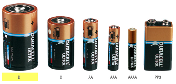
The device is powered by two D cells.
The device has two built-in sensors:
- one motor, activated during 2 seconds on user requests,
- one switch, closed when the device is not in maintenance.
Objective
The connected device has to count the number of user requests (motor activation), and send it to a platform when the maintenance mode is activated (switch open).
Communication
As the device will be placed in a lot of environment, and is battery powered, I chose to use the Sigfox network (see coverage).
Note: If the network seems quite good outdoor, it is not easy to have a good signal indoor, even in Paris area.
Hardware selection
Network
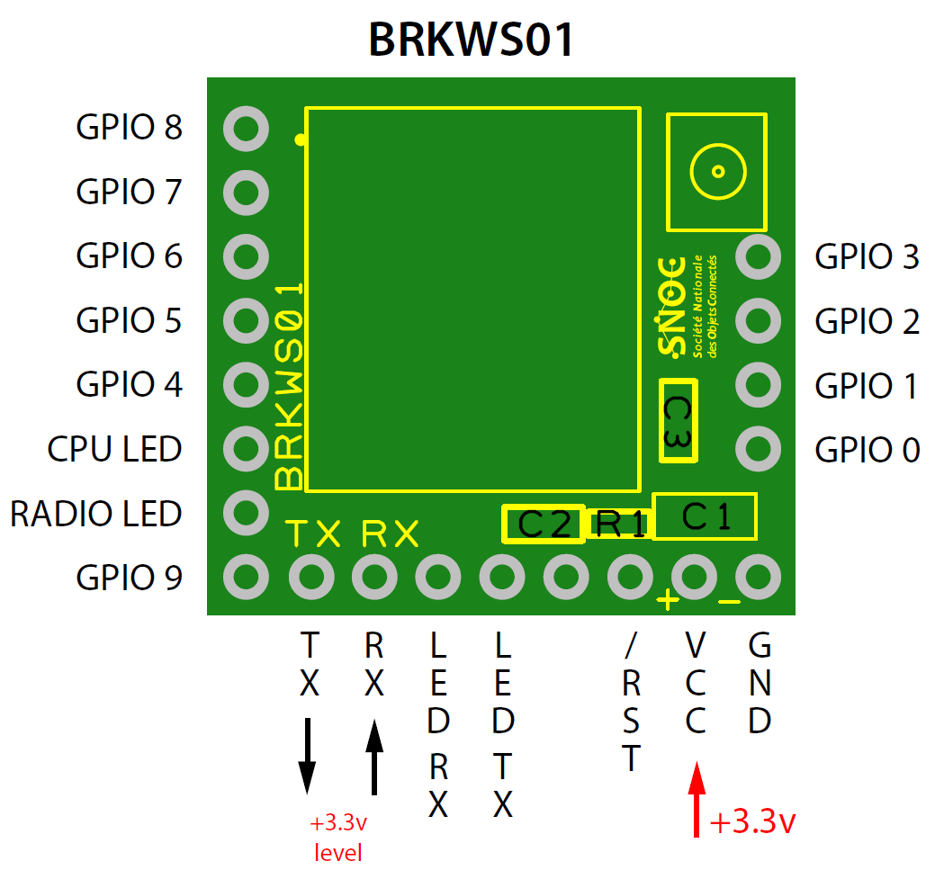
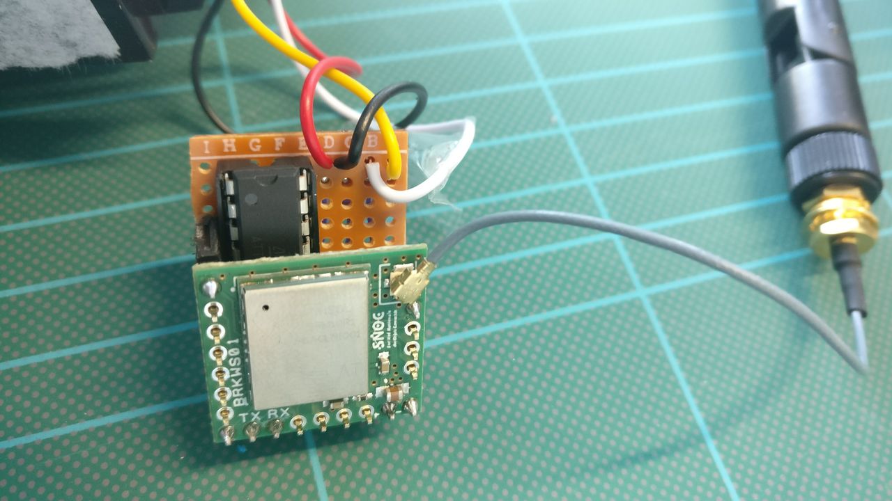
I found the Sigfox Breakout board BRKWS01 (+ Antenna) around 20€, with one year subscription included.
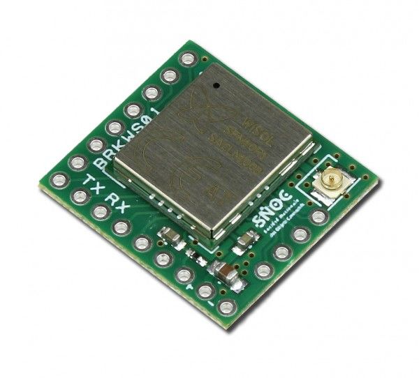
It's a little module (around 2cm side) based on the Wisol SFM10R1 chip. The included firmware respond to AT commands on the serial port of the board. For a quick and dirty PoV, it's perfect.
This module can work between 1.8V and 3.6V, which is perfect for my 2 cells Alkaline battery powered device.
In sleep mode, the module only consumes 2µA.
By default, the Sigfox module is configured to use 9600bps.
MCU
I wanted a compact DIY solution (DIP), low power, cheap and equipped with an hardware serial port.
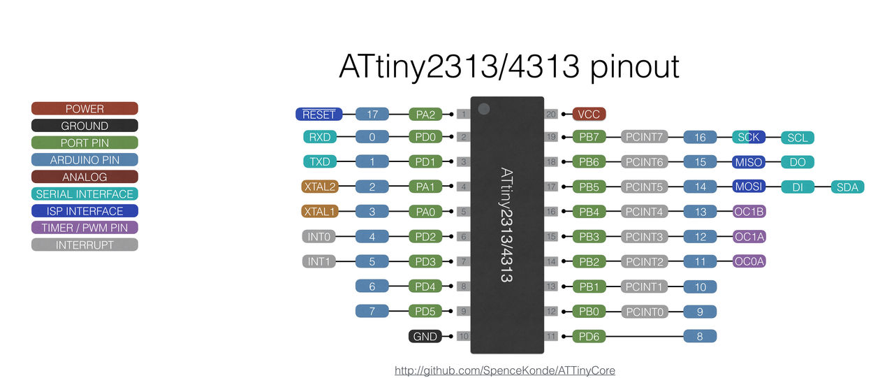
I chose to use an ATtiny2313A, which consumes less than 0.1µA at 1.8V.
The memory is quite limited, but enough for this little project.
Moreover, it can be use without any external component.
To flash the ATtiny (DIP package), I used a little perfboard circuit.
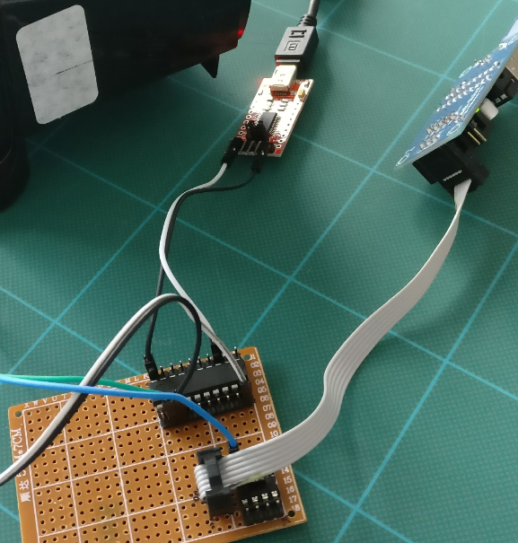
The ATtiny is flashed with an USBTinyISP programmer, and I listen to the Serial output with a Serial-USB converter.
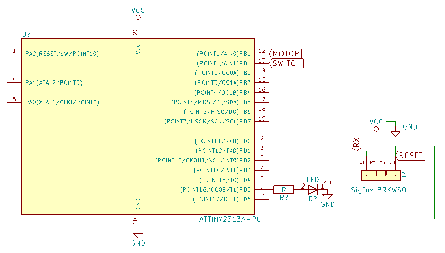
Circuit
If I had to redo it, I will add two decoupling capacitors (between Vcc and GND):
- 10µF tantalum capacitor
- 0.1µF capacitor
Source code
The source code is available on Github.
Power consumption
To have a low power consumption, the ATtiny sleeps most of the time. Same behavior for the Sigfox module.
The Sigfox module is woken up with a 500ms LOW pulse on the RESET pin. After that, the Sigfox module needs around 1s to be ready.
AVR speed and serial
The device fuses are set to run at 1Mhz. At this speed, it is complicated to run the serial port at 9600bps.
For that, you have to set the U2Xn register to '1', and the UBRR register to '0x00C'. For that, I used the 'USART2313' library.
AT commands and messages
The messages contains the number of activation in HEX format.
I wanted to use the 'sprintf()' function, but it is too much for the small ATtiny flash, so I had to use a dirty hack.
Only few AT commands are used:
ATused twice to initialize the moduleAT$SF=XXX+ CR : send an up-link messageAT$P=2: enter deep sleep modeAT$I=11: get the PAC number to identify it and add it on the Sigfox backend.
Wake-up on motor & switch state change
To wake-up when the motor is activated or when the switch state changes, I used the PCIE interrupts. Sadly, the INT0 and INT1 cannot be used to detect a pin change.
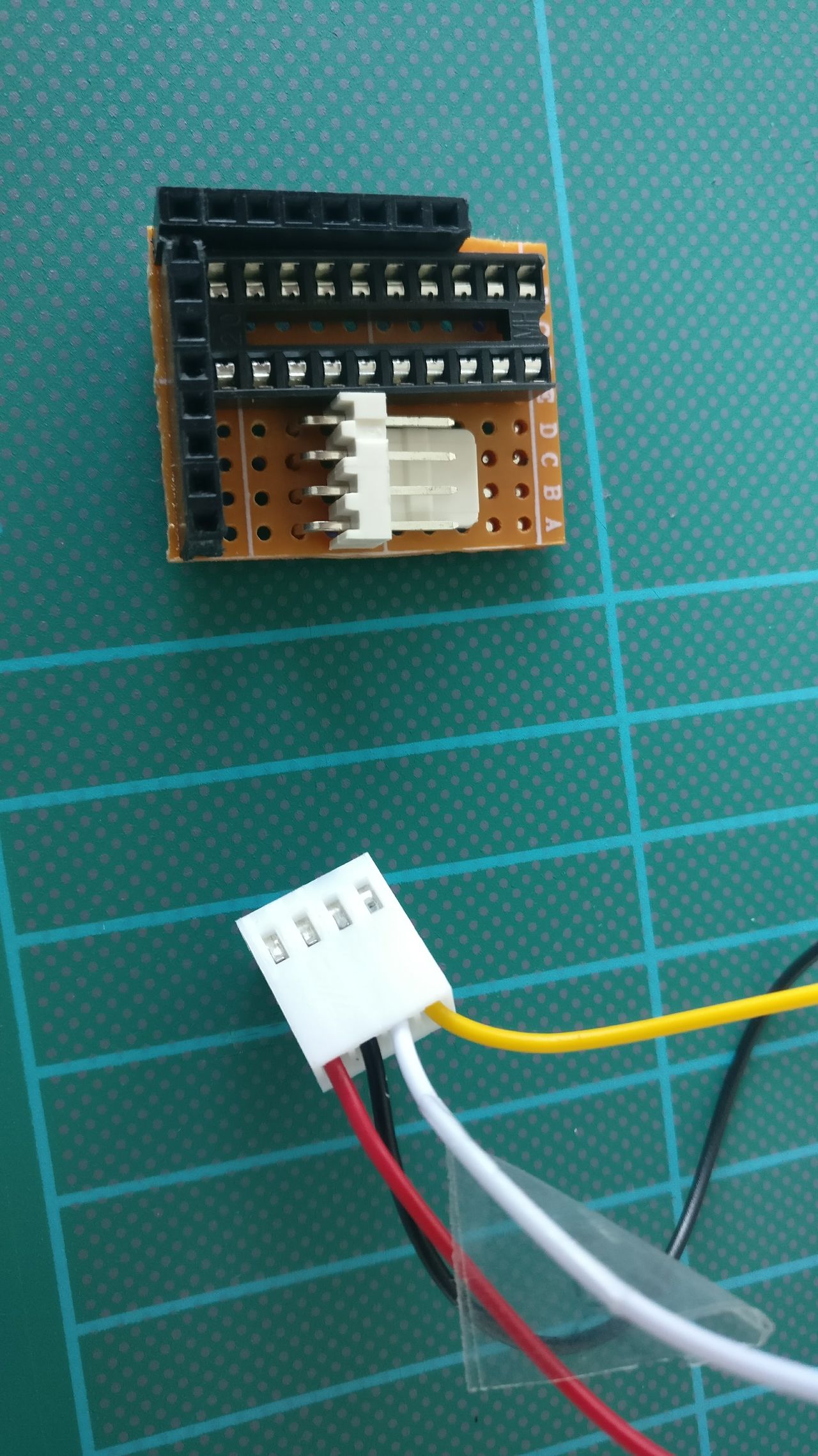
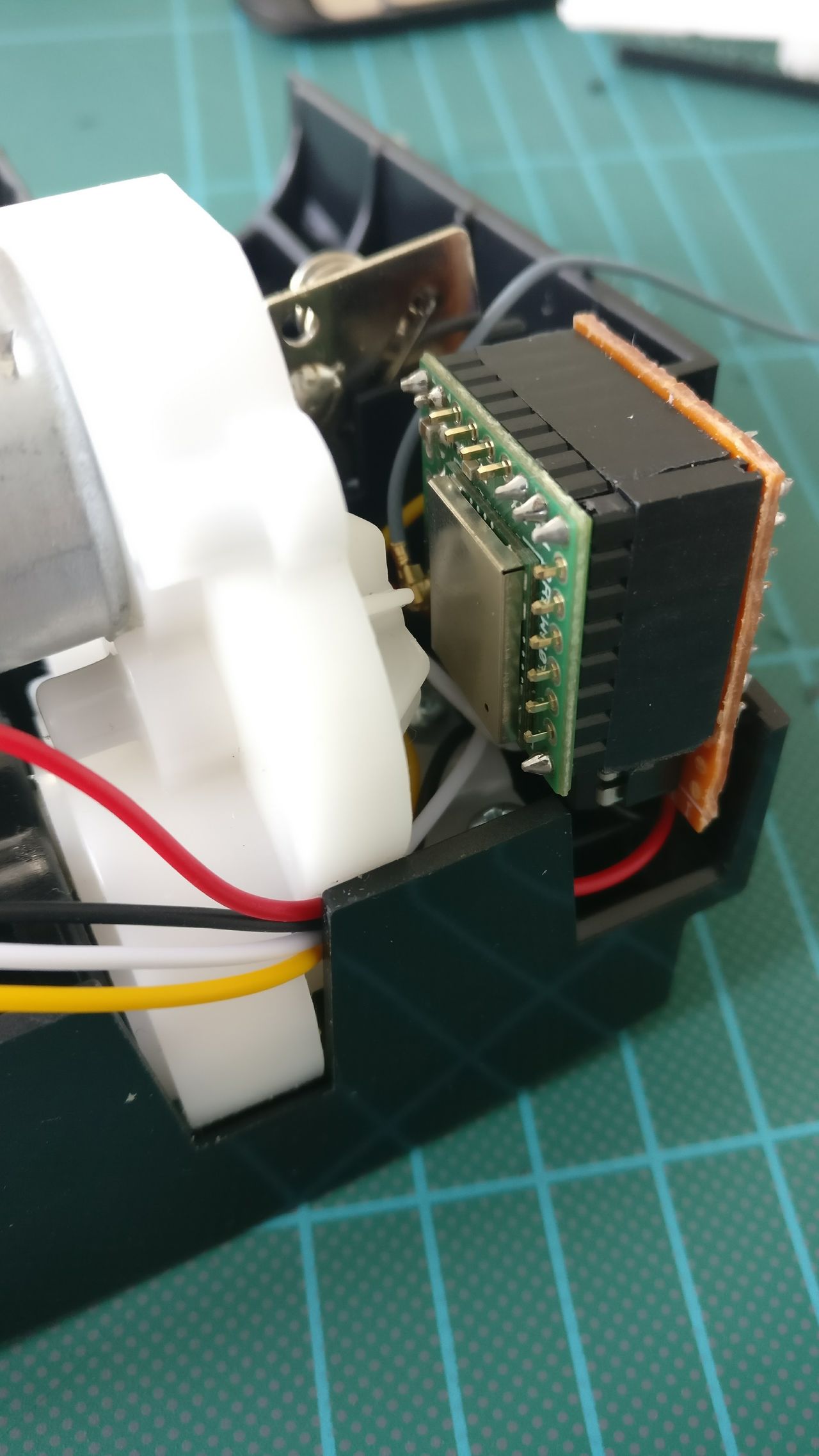
Device integration
Once the program tested, I added some wires to power the card, and to me linked to the motor and the switch.
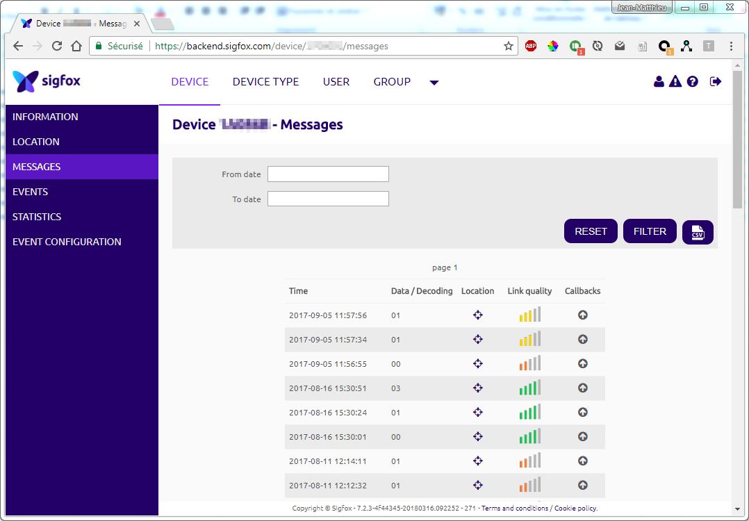
Sigfox backend
Once the device added on the Sigfox backend, we can see the messages coming in.
Conclusion
Easy and quick prototype for a PoV. It still works few months later, with a very low power consumption of 0.4µA in deep sleep mode. In active mode, the battery consumption (around 40mA in transmission - few seconds) is negligible compared to the consumption of the DC motor.
If I have the opportunity, I will:
- add the 2 capacitors to avoid any issue linked to the motor power consumption,
- monitor the battery level (sadly, the ATtiny2313 doesn't have an ADC functionality)
- wake-up at least once every 24h with the watchdog to send the current count,
- find a way to know if the network is realable or not when installing the device (i.e. send a message on a button press, requesting a down-link and a red/green LED to indicate if the down-link has been received)