Water tank monitor [4]: Source code
After building the circuits of the sensors and the base station, it's now time to program them with the Arduino core.
![Water tank monitor [4]: Source code](https://storage.ghost.io/c/fe/14/fe1439bb-44cb-4fc0-aa30-44bf49d2ab9f/content/images/size/w2000/2016/08/water-tank-monitor-cover-4.png)
In some previous posts, I built the circuits of the node sensor and the base station of this project.
In this post, I will explain the source code I wrote for each circuit.
RF considerations
nRF24L01+ remarks
Before using this modules, please note:
- This module cannot be used to emit and receive at the same time. However, you can switch between those modes;
- You can set the speed of the network transmissions. Higher the speed, lower the range;
- Each device can receive / emit on some addresses (by creating software pipes);
- A module cannot listen on more than 6 addresses at the same time;
- You can select a channel (between 0 and 125) shared by all your devices. This can be useful if a channel is already full of wifi waves);
- The payload size of each data frame can be a static or dynamic;
- An low level acknowledge can be activated / disabled independently on each pipes. If you do so, be careful not to have more than one device emitting with the address used; otherwise, more than one device could receive the acknowledge;
- A payload can be added to the acknowledge, but it has to be done before receiving the message to acknowledge (i.e. you cannot compute the acknowledge with the content of the received message);
- An auto-retry can be activated, when acknowledges are enabled;
- A CRC can be managed by the module itself.
High range
As I don't need to send a lot of data to the base station, I tried to maximize the range of my devices, at the cost of energy and data transmission speed.
As such, I used my RF emitter with the following configuration:
- Speed: 250kbs (RF24_250KBPS)
- Power amplifier (PA) level: -6dBM (RF24_PA_HIGH)
Message protocol
As I don't have a lot of time, I will simply transmit the value (in centimeters) of the sensor reading (unsigned short - 2 bytes), and the address of the sensor ("0x01" or "0x02", 1 byte).
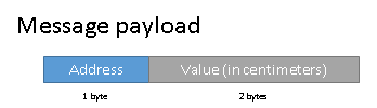
// - Message definition
typedef struct {
  // - Address of the device
  uint8_t address;
  // - Value of the sensor in centimeters
  unsigned short value;
} Message;
In this first version of the solution, I will use some libraries, but managing by myself the RF communication, the low power mode, and so on. It's important to understand the basics before using another solution (like a IoT framework).
I think that in the next version of my solution, I will use "mysensors.org" as the base software for the sensor node and the base station (transformed into a real gateway).
RF addresses
In RF, each device should be identified with an unique identifier. This identifier should be used to map transmitted sensor values to a functional meaning. This point is not addressed in the following paragraph.
The future
To be able to create a star network in RF, each device should have a specific RF address.
However, I don't want to store the address in each device in the source code.
Sadly, I don't have enough time to write a good messaging protocol, but, if I had enough time, I would like to address this point like that:
-
Three types of addresses are defined:
- A "broadcast" address (for example "255"):
- Used by a node in "pairing" mode
- A gateway address, known by all nodes (for example "0")
- Node addresses, distributed by the gateway
- A "broadcast" address (for example "255"):
-
When a node doesn't have an address (e.g. brand new), it sends an "address" request on the gateway address. The gateway sends a response on the "broadcast" address.
-
The node receives its address:
- stops listening on the broadcast address;
- starts listening on its own address.
-
When a node transmits a sensor value, it does it on the gateway address.
In a simple implementation, the gateway manages the addresses on the RF level. On a bigger picture, maybe the "cloud" part will have a role to play.
In reality
For now, as I only have two nodes, I will not care about this point. But this will be an important aspect on the 2nd version.
In this version, the gateway have the address "0", and the sensor nodes use the address "1" or "2", depending on the jumper state (open or closed).
// - Read address selection
pinMode(ADDRESS_SELECTION_PIN, INPUT_PULLUP);
if(digitalRead(ADDRESS_SELECTION_PIN) == HIGH) {
  nodeAddress[0] = 0x01;
} else {
  nodeAddress[0] = 0x02;
}
Development environnement
For this first project with Arduinos, I used PlatformIO with Atom IDE.
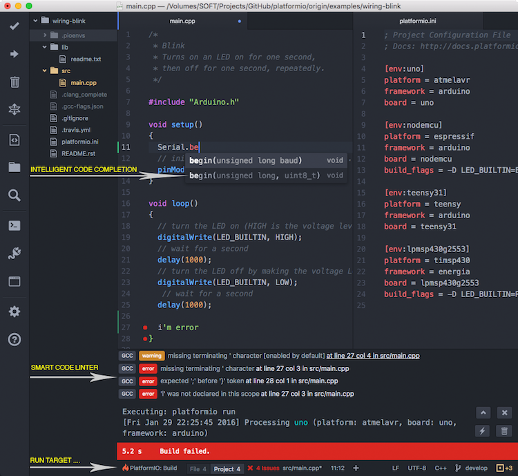
It's really simple to use and understand. Moreover, with the v2 version, you can download external libraries (but not a specific version, this will come with v3), without adding it into your source code folder.
I used this trick on my projects, so please be careful to install the necessary dependencies, listed in the README file of each project (and check the versions).
Arduino libraries
Low Power
For managing the low power mode of the Arduino, I use the LowPower library.
RF24
To use the nrf24l01+ and send messages, I use the optimized fork of the RF24 library.
NewPing
To use the HC-SR04 with few functions, I use the NewPing library
Sensor node
On this first version of the node, the sensor node has to:
- During "setup":
- Configure PINs
- Memorize the device address (jumper state)
- Configure radio module
- On "loop":
- Power-up the sensor & level shifter;
- Read 5 times the distance sensor / water;
- Power-down the sensor & level shifter;
- Forget the first reading (always KO);
- Create an average value of the readings;
- Power-up the radio module;
- Sends the value to the gateway;
- Power-down the radio module;
- Sleep for a while (12h ?)
I published the source code with a lot of comments on GitHub.

Please note that the jumper used to define the RF address, is in "pull-up" mode, avoiding the use of an external resistor. This jumper prevents me to change and flash the firmware to change the RF address of the node. All I need to do is turn off the device, remove / add the jumper, and turn it on again.
Base station
In this first version, the base station will listen for any messages, and blink the first or the second LED, depending to the RF address given in the message.
It will allow me to make a dry run on the chalet tank.
I also added a LED color scale indicating the current distance between the water and the sensor:
- Red-ish : Water tank (near) empty
- Orange / Yellow : Water tank in use :P
- Green-ish : Water tank (near) full
As the sensor node, I published the source code with a lot of comments on GitHub.
Video
For this video, 1 message is emitted every second.
Next step
We've got the first version of the node and the base station. Now, it's time to look for the power consumption, and improve it as much as possible.