Water tank monitor [3]: Circuits
Time to build my first water taken sensor and the base station! I will use perfboards and plastic boxes for this first iteration.
![Water tank monitor [3]: Circuits](https://storage.ghost.io/c/fe/14/fe1439bb-44cb-4fc0-aa30-44bf49d2ab9f/content/images/size/w2000/2016/08/IMG_0501-1-.jpg)
On the previous post about the water tank monitor, I chose the components of the base station and the sensor node.
I tried the components on a breadboard, independently of each other. However, I'm willing to test the solution on the water tank very soon. As such, I have not enough time to make all the circuits on the breadboard, and will solder the components quite quickly.
It's time to build the circuits!
nRF24L01+ pinout
To use the nRF24L01 module, you have to use the following pinout:
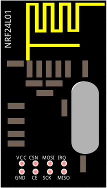
I used the following pins on the Arduino:
| PIN | NRF24L01 | Arduino UNO |
|---|---|---|
| 1 | GND | GND |
| 2 | VCC | 3.3V |
| 3 | CE | digIO 7 |
| 4 | CSN | digIO 8 |
| 5 | SCK | digIO 13 |
| 6 | MOSI | digIO 11 |
| 7 | MISO | digIO 12 |
| 8 | IRQ | - |
Base station
The base station is composed with:
- Arduino Nano (5V), with USB port as main power supply
- NRF24L01+ (PNA / LNA in option)
- 2 RGB LEDs to indicate the level of each tank
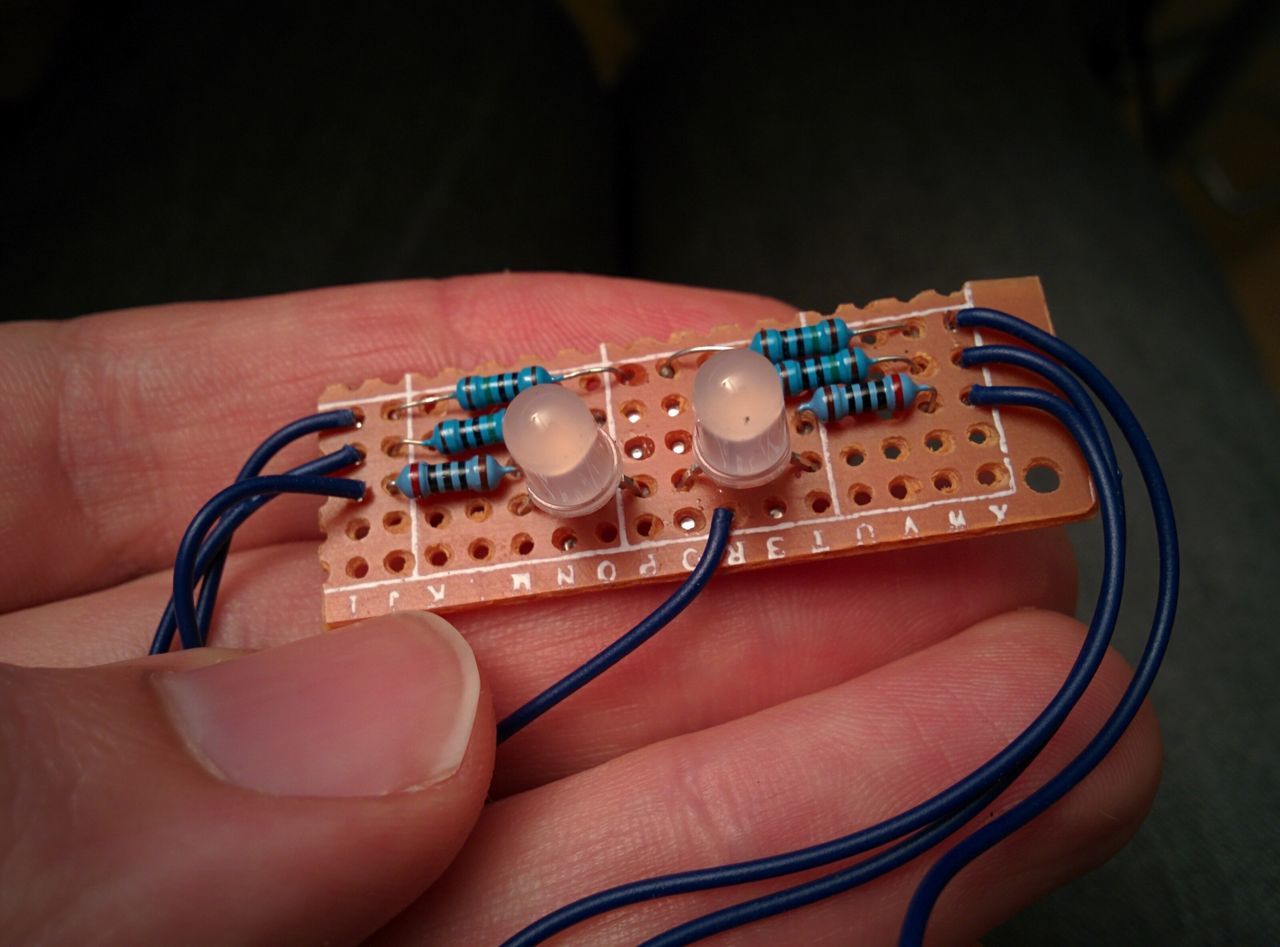
RGB LEDs
The LEDs are driven by the Arduino digital outputs with PWM). It will allow me to create a color scale from red to green.
RGB LED characteristics:
    Forward Voltage (RGB): (2.0, 3.2, 3.2)V
    Max Forward Current (RGB): (20, 20, 20)mA
    Max Luminosity (RGB): (2800, 6500, 1200)mcd
Rred = (5 - 2.0) / (16 * 10-13) = 188Ω ~ 200Ω
Rblue-green = (5 - 3.2) / (16 * 10-13) = 113Ω ~ 150Ω
As I plan to create a color scale with the red and green leds, I connected them to some digital PWM pins of the Arduino Nano.
For that, I used the pins D5, D6, D9 and D10.
The blue LEDs are connected on some classic digital pins.
Note : I planned to try soldering SMD components
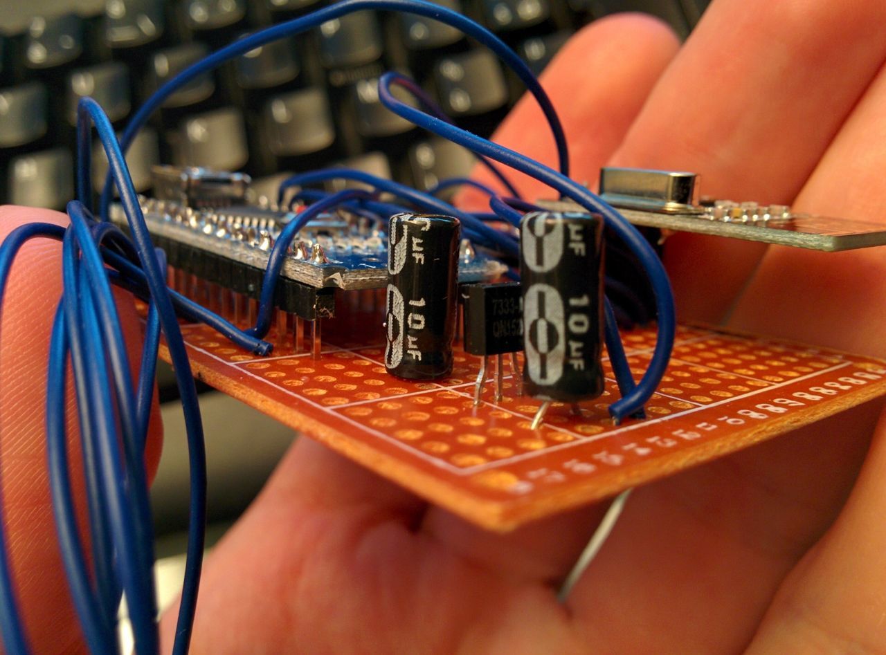
3.3V regulator
In the future, I will using an ESP8266 in my base station. And maybe an NRF24L01+ with PNA/LNA.
To avoid using the 3.3V from the Arduino Nano, quite limited in power, I added a small LDO, named HT7333, in TO-92 package, with two 10µF capacitors. It can supply 250mA, and have a low quiescent current.
I'm not sure that's the best choice, but it was in my possession.
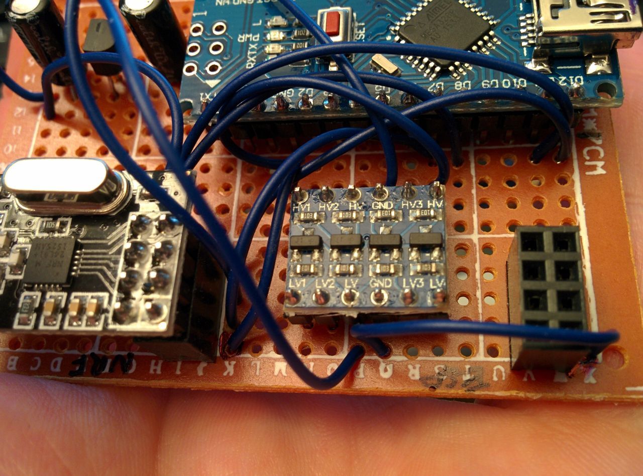
Building the future
At first, I wanted to add an ESP8266. As I don't have time right now, I just added the PIN slot, and the level shifter on the perfboard, without connecting it entirely.
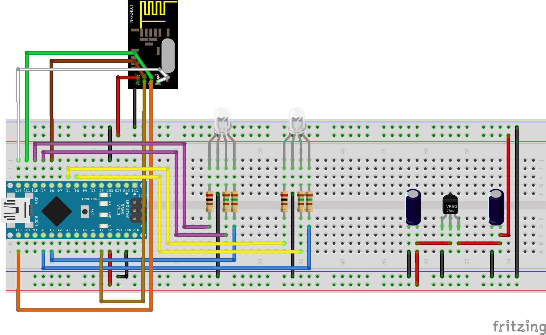
Circuit schematics
As I said before, I didn't really build this circuit on a breadboard, but only on the perfboard.
Please note that the HT7333 is symbolized with the 78xxl component on the perfboard.
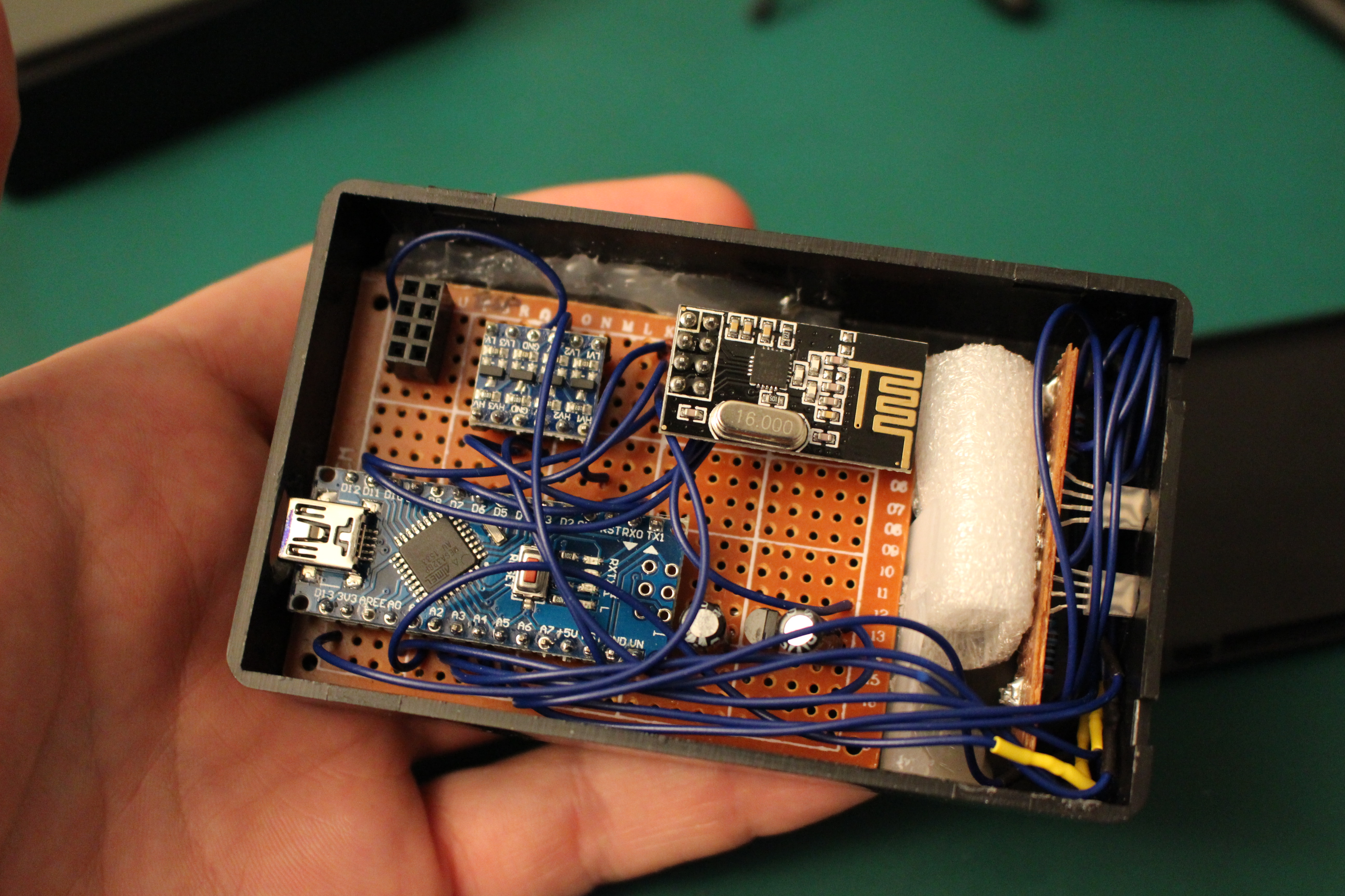
Pictures
Remark: As the box is pretty small, I had to directly solder the Arduino Nano and the level shifter on the perfboard. Normally, I should use some pin slots.
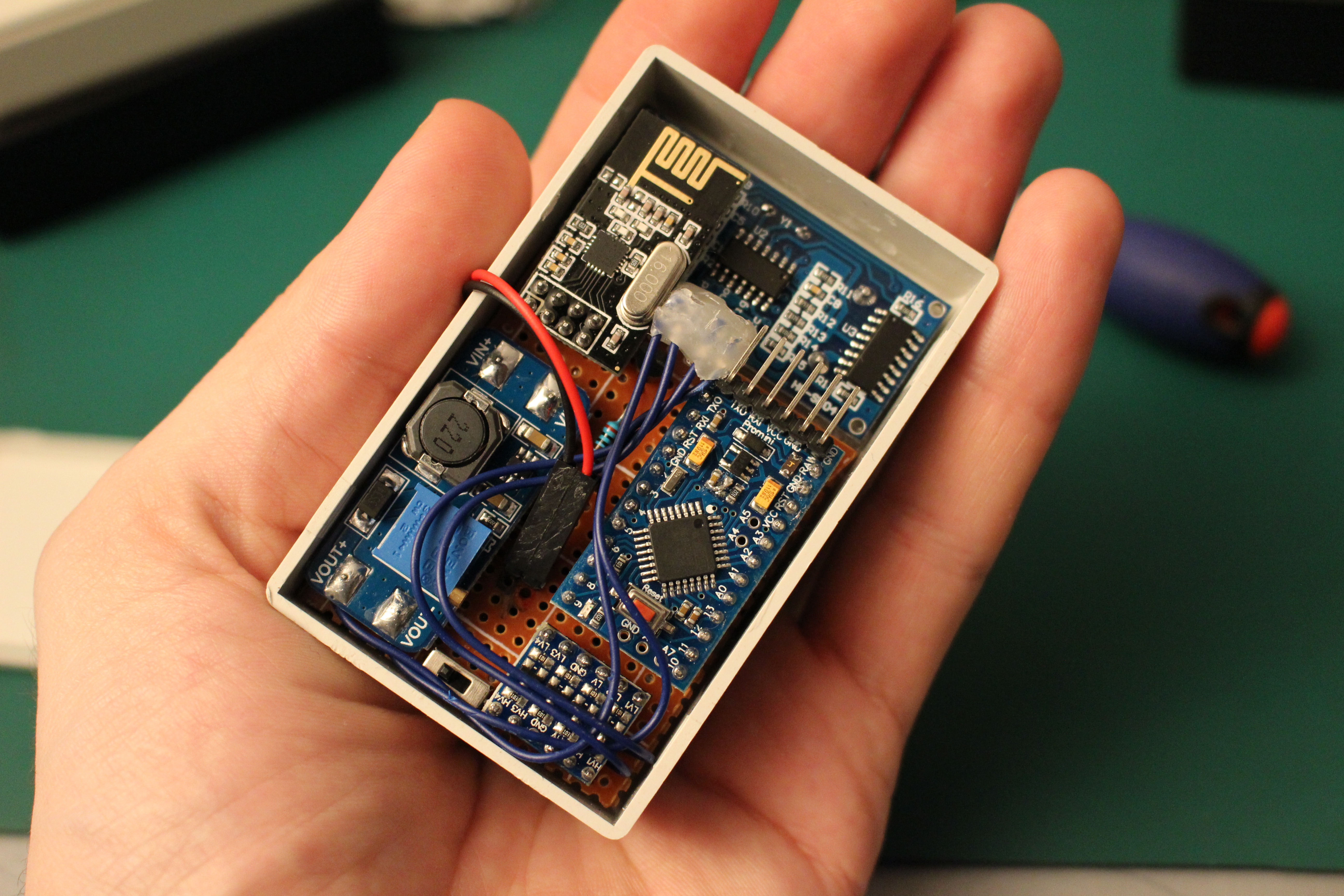
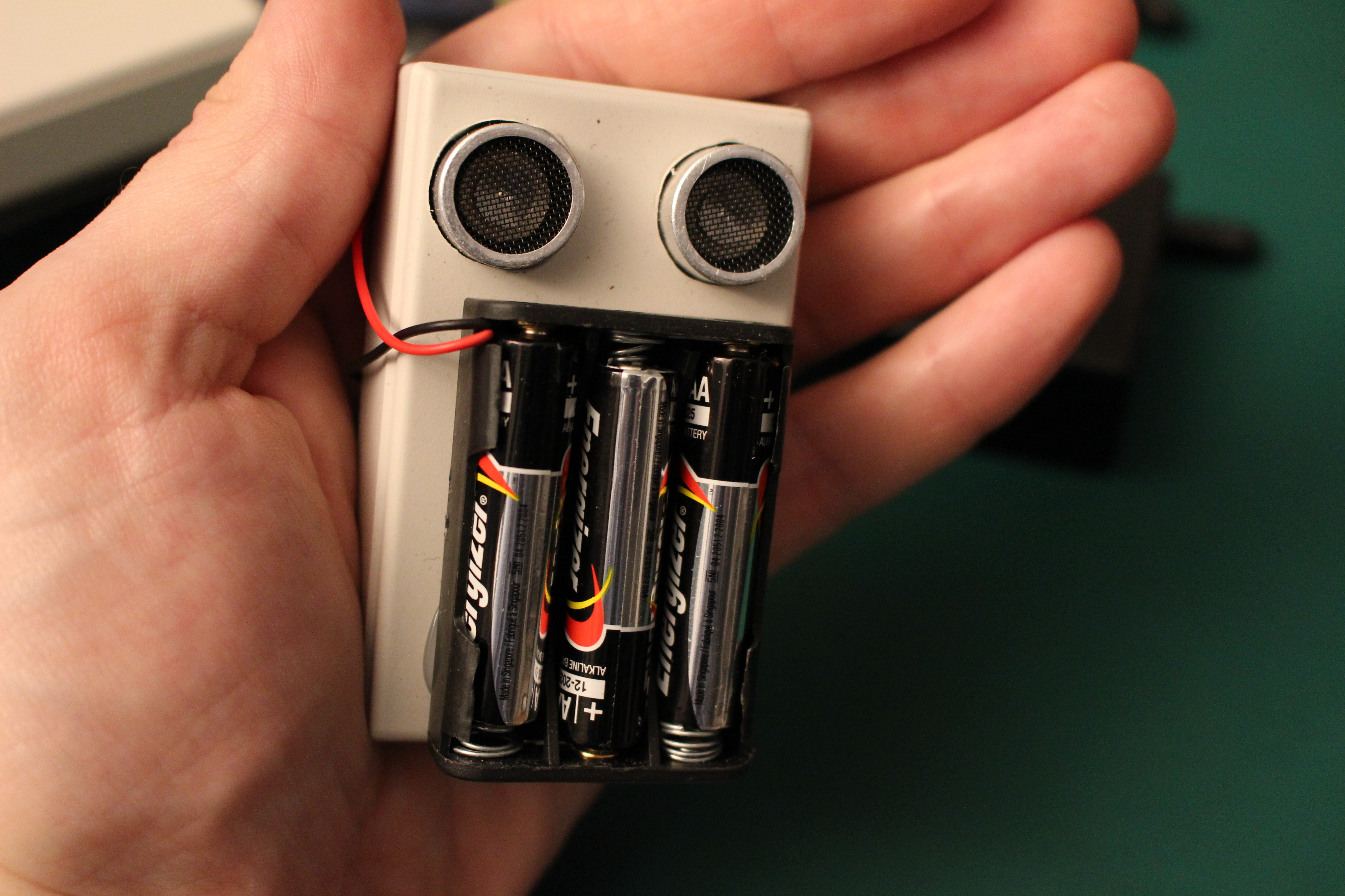
Sensor node
The sensor node is composed with:
- Ultrasound distance sensor HC-SR04
- Arduino Pro Mini 3.3V@8Mhz
- NPN2222 + resistor
- Level shifter (3.3V / 5V)
- nRF24L01+
- DC-DC Step up MT3806, adjusted to 5V output
The DC step up converter powers the level shifter and the sensor (5V).
The NPN allows me to power on/off the DC step up converter.
I'm not sure that this circuit is a good practice, because the level shifter and the sensor will not be connected to ground until the NPN will allow it.
I will try to change the NPN by a mofset on a future version of the circuit.
I used a 2kΩ resistor on the NPN base, computed for IC = 60mA (max), and hFE = 75 (from the datasheet).
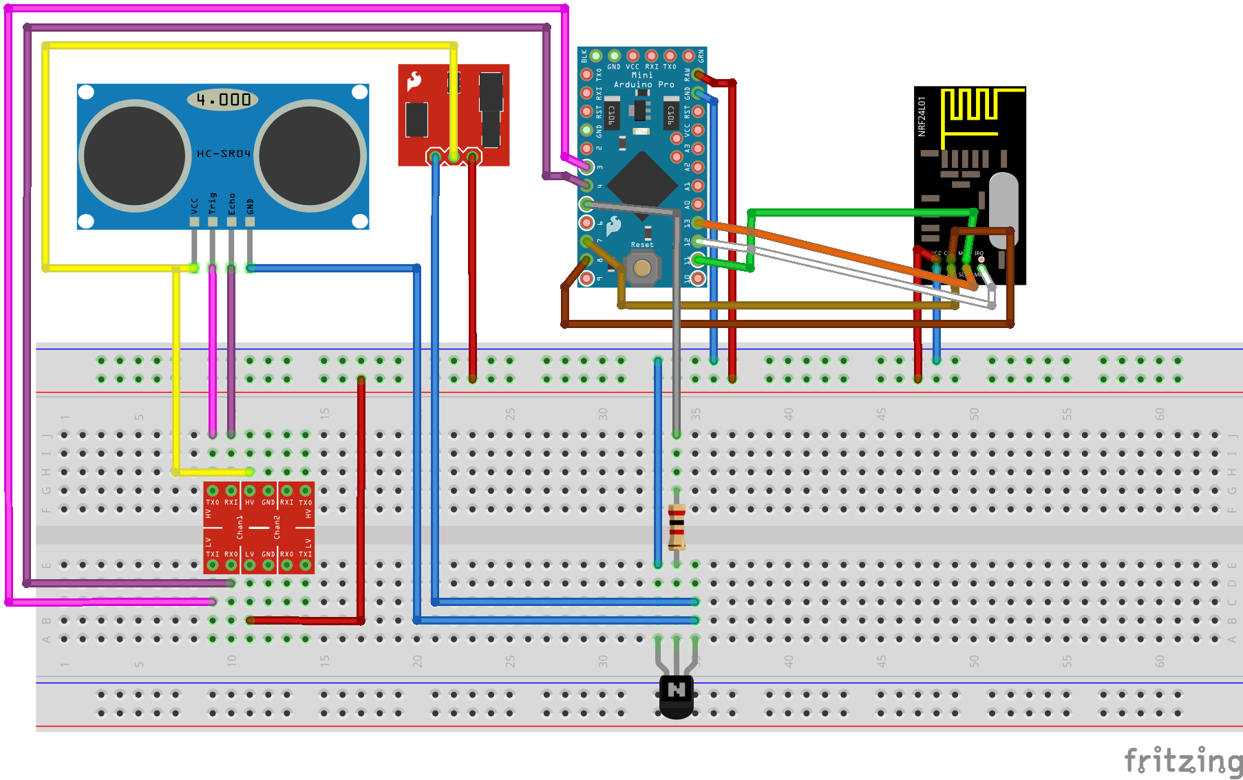
Circuit schematics
As I said before, I didn't really build this circuit on a breadboard, but only on the perfboard.
Please note that I used cheap components instead of sparkfun level shifter and step-up converter.
A small jumper has also been added, linking pin 9 to the ground. It will be used to define which tank is measured.
Pictures
Remark: As the box is pretty small, I had to directly solder the Arduino Pro Mini, the step-up converter and the level shifter on the perfboard. Normally, I should
use some pin slots.
Remark 2: For the same reason, I created bent a connector for the sensor.
Next step
Now that all the circuits are ready, it's time to implement the functionalities of the base station and the node sensor.
Moreover, we will try to use the node sensor in a low power mode.