Fashing the ESP12E with the breadboard adapter
The ESP8266 is a great way to build connected projects. I love using the barebone chip with the breadboard adapter. Let's see how we can flash it!
In a previous post, we saw how to flash an ESP-01.
Today, I want to flash an ESP-12E with a breadboard adapter.
Adapter
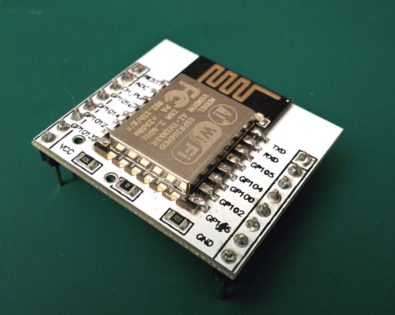
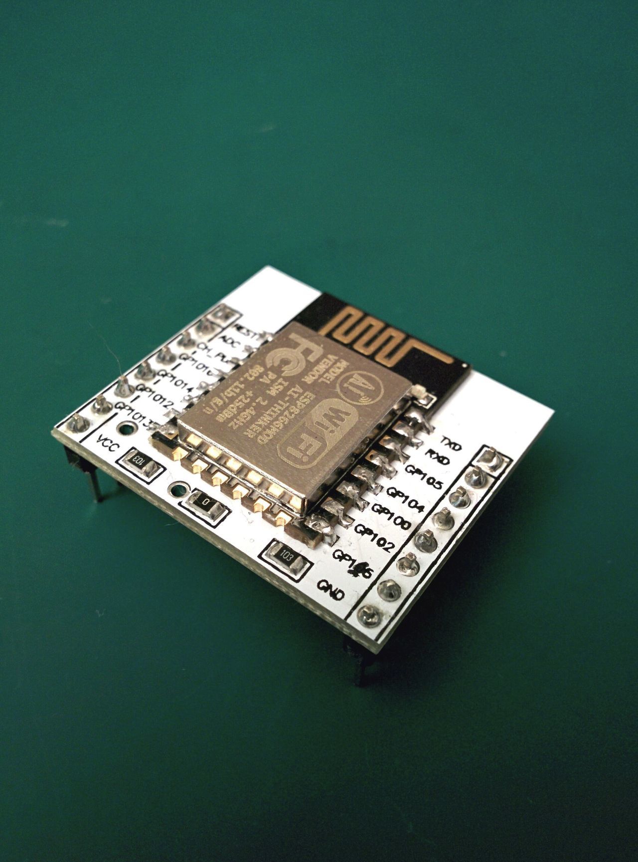
We need an adapter, because the pin wholes of the ESP-12E are not spaced enough to be directly plugged on a breadboard.
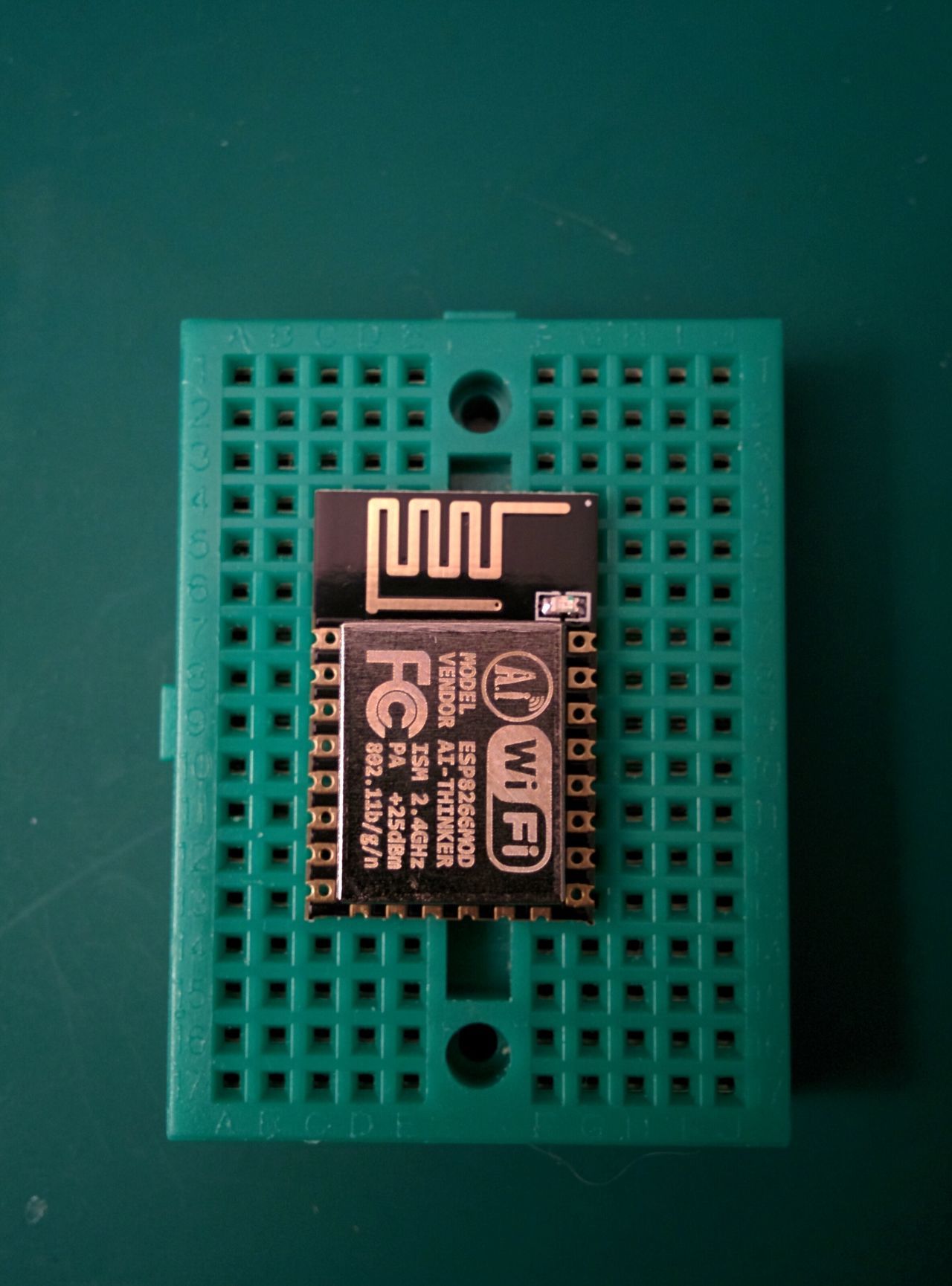
Some folks solder a wire on each ESP-12E pin, but I think it's easier to just use some adapter.
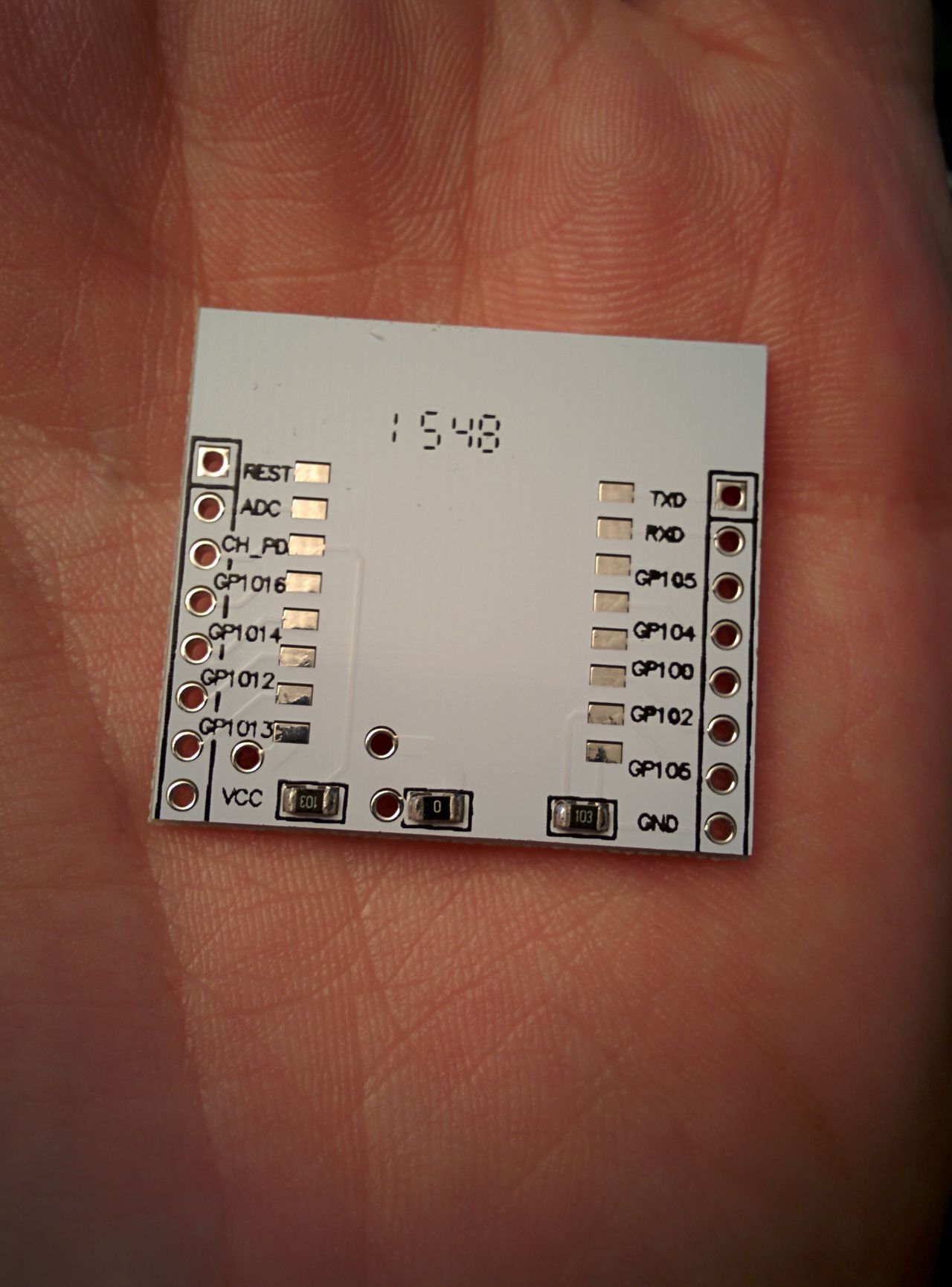
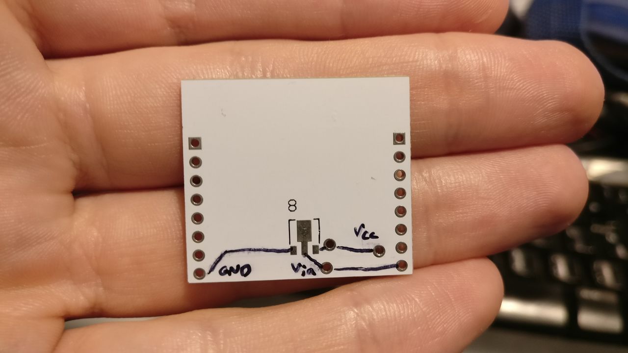
If you look closely, you will see some resistors on the adapter.
Please note that the GPIO05 on the bottom/right of this adapter is in reality the GPIO015. I will by better adapters next time !
As the ESP-01, some pins have to be LOW or HIGH depending on the state of the ESP8266.
CH_PD: HIGH
GPIO 0: High in normal mode, low on flash mode
GPIO 2: High[1]
GPIO 15: Low
The resistors have a value of 10kΩ, and set GPIO15 to Low, and CH_PD to High.
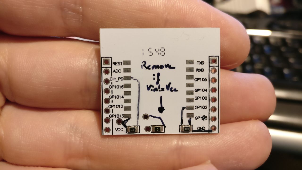
There is also a 0-resistor, and some connectors under the adapter. The connector can be used to add an HT7333, and removing the 0-resistor. The Vcc pin is then transformed to a Vin pin.
So, after soldering the ESP to the adapter, all that I had to do was:
- Connect a button between the reset pin and the ground, with a pull-up resistor;
- Connect a button between the GPIO0 and the ground, to switch between normal mode and flash mode.
Perfboard modification
I modified the perfboard card that I use to flash an ESP-01.
For some reasons, it didn't seems to work the first time, so I draw the schematic to check the circuit.
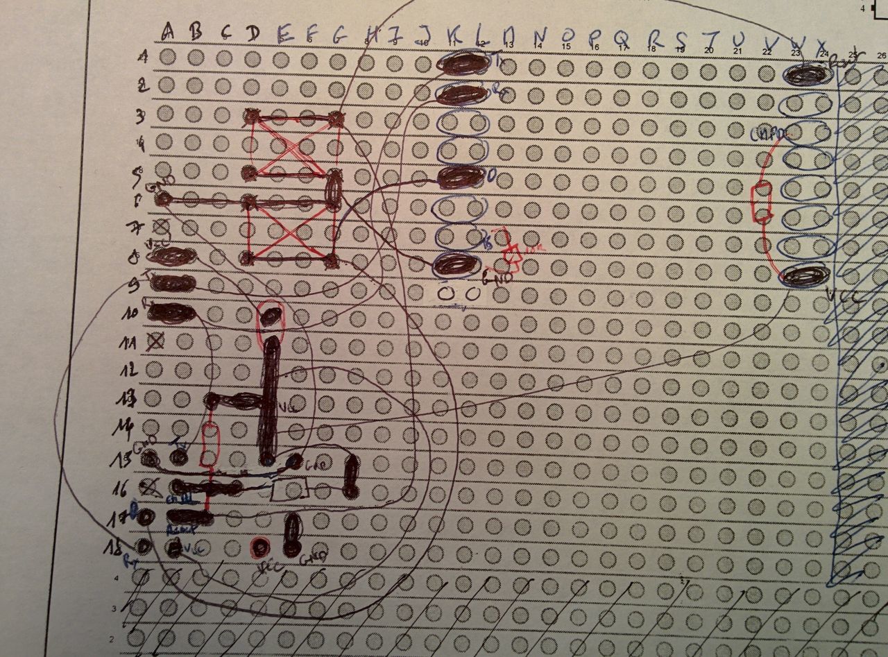
And it was OK (but awful, right ?). On the second try, it was working pretty well (bad connection maybe ? Or GPIO2 ?[1:1]).
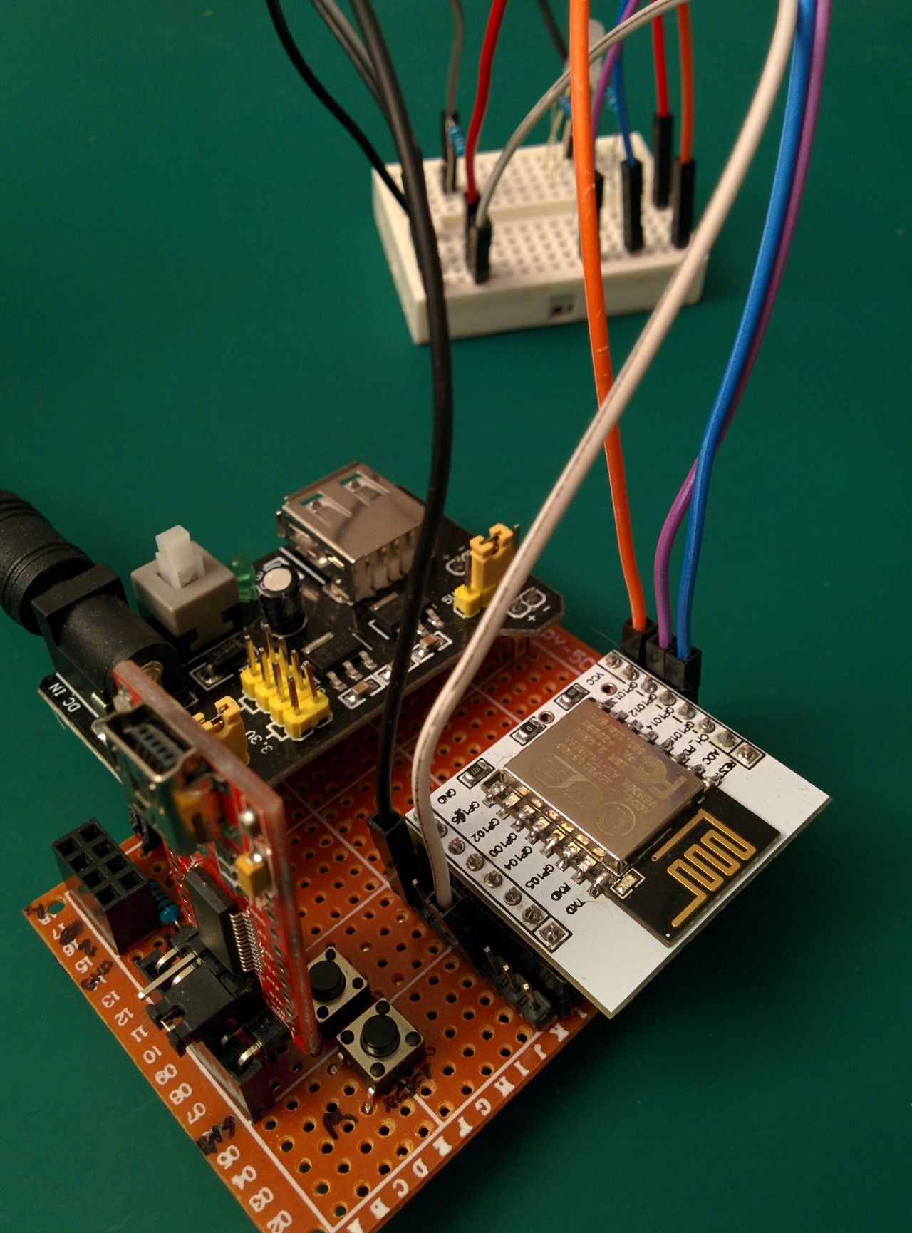
I launched a Putty terminal on the COM port, on 9600 bauds, and pressed the reset button, and type "AT+GMR" + Enter key...
> AT+GMR

AT version:0.40.0.0(Aug  8 2015 14:45:58)
SDK version:1.3.0
Ai-Thinker Technology Co.,Ltd.
Build:1.3.0.2 Sep 11 2015 11:48:04
OK
Hurrah!
Flash
If you want to flash the Expressif firmware, you can download it on the ai-thinker blog.
You can also use the NodeMCU firmware.
For flashing my ESP-12E, I used the NodeMCU Flasher. I will try esptool.py another time...
As for flashing the ESP-01:
- Select the firmware in NodeMCU flasher, on adress 0x00000
- Press and hold RESET and GPIO0 buttons
- Click on the "Flash" button
- Release RESET button
- When the progress bar begins to fill, release the GPIO0 button
- And wait the end of the flashing process.
Next step
Now that I flashed an ESP-12E without all the dev kit around it, I will try to deploy my freezer door project on it.
Maybe later, I will also try to avoid pushing GPIO0 and RESET buttons, using some other signals provided by the RS232/USB adapter.