Pulse LED with ATtiny
The ATtiny opens new low costs project possibilities. Pulsing a LED for few seconds is an easy example.
After pulsing a LED with a NE555 when the light is on, I want to create the same kind of behavior, but only pulse the LED during few seconds.
To do that, I will use a ATtiny instead of a NE555.
The circuit will be mounted on a 6V powered device.
To consume as little power as possible, the ATtiny will have to run @ 1Mhz, which means that I have to power the device between 2.7 and 5.5V to be compliant with the datasheet.
Expected behavior
- When the device is powered on, the LED will blink
- Device goes into sleep mode
- When the light goes on, the device wakes up and pulse the LED
- After 5 pulses, the LED goes off and the device does into sleep mode
Components
- 1x LDR (here GL5528)
- 1x variable resistor to tune the level of detection
- 1x ATtiny85
- 1x LDO 3.3V circuit (here HT3333 + 4 capacitors)
- 1x White LED + resistor
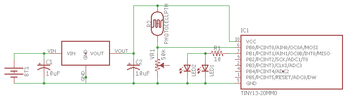
Circuit
Please note that I forgot to add the two 0.1µF capacitor between GND-Vin and GND-Vout.
Source code
To limit the power consumption, the ATtiny will be in deep sleep mode.
The LDR sensor pin will be activated as an external interrupt (PCINT).
At first, I wanted to use the INT0 interrupt, as it is possible to configure it for rising edge only (light off to light on) interrupts, but INT0 needs a clock for working, and in deep sleep mode, the clock is disabled.
Instead, I used the PCINT0 and the associated vector to detect any kind of level change on the PB0 pin.
In the vector associated source code, I check if the level is low or high on the input pin, which gives me a kind of software rising edge check.
The source code has also been changed to manage the ATtiny13a, by removing the call to the "sin()" function. So, for the ATtiny13a, the LEDs are configured to blink and not to pulse.
See the full source code on GitHub
First circuit with a Digispark board
I have a digispark clone device, with an ATtiny85 running at 5V @ 16MHz.
This device will allow me to built a proof of concept on breadboard before going on perfboard at 3.3V / 1Mhz.
For this circuit, I will replace the LDR + variable resistor with a small button to GND, and the input pin will be configured with internal pullup resistor enabled.
Instead of an external LED, I will use the buildin LED of the digispark board.
With the LDR
I replaced the switch by an LDR and a variable resistor.
With the digispark at 5V, I used an 100kΩ variable resistor.
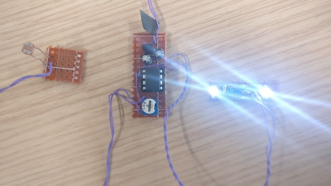
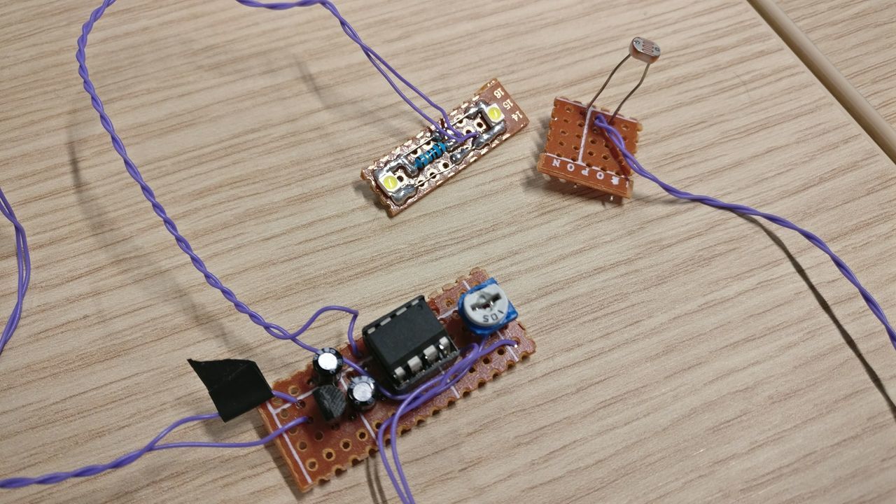
On perfboard
Going at 3.3V / 1Mhz
To be able to use our ATtiny at 3.3V and 1Mhz, I discarded the Nucleus bootloader of the ATtiny, and I flashed the firmware directly with the USBTinyISP.
The fuses have to be changed:
- SELFPRGEN is now unset
- The clock source is changed to select the internal oscillator @ 8Mhz
- CKSEL0 is unset
- CKSEL1 / CKSEL2 / CKSEL3 are set
- CKDIV8 is now set (so the clock is divided by 8)
In details :
- Low fuse: 0x62
- High fuse: 0xDF
- Extended fuse: 0xFF
Circuit
The LED used is an white LED 3528. The max current is 20mA and the voltage should be between 3.0V and 3.4V.
As the ATtiny has the capability to output 40mA per I/O Pin, I can power two LEDs with the selected PIN.
So, to power my two LED in parallel (16mA per LED), I will use one resistor, with
R = U / I = 0.3 / (16 * 10-3 * 2) ≈ 10Ω
and P = U * I = 0.3 * (16 * 10-3 * 2) ≤ 1/4W
As I use 1/4W resistor, I want to be sure that they will not exceed the max power.
Video
To define the light level necessary to turn the LED on, use the variable resistor. A multimeter can help you find the "HIGH" level (2.4V for 3.3 logic level), between the sensor pin and GND.
ATtiny13A (blink)
ATtiny85 (pulse)
Power consumption
I measured the LDR and the variable resistor after calibration.
- Lights on, RLDR+R = 9kΩ
- Lights off, RLDR+R >= 150kΩ, and goes even over 1MΩ,
so, in theory, for LDR+R, Imax = U / Rmin = 3.3 / 150k = 22µA
And I measured the power consumed by the circuit in some configurations, with V
- Lights off (LDR in the dark):
- Icircuit-max: 22µA
- IATtiny < 0.2µA, the ATtiny really goes into low power mode.
- Theoretical:
- LDO: 2.5µA
- ATtiny: around 0.1µA
- LDR: around 22µA
- Lights on:
- With LED on: around 15mA (lot less than expected with the two LEDs)
- With LED off: 420µA
To conclude, with a consumption lower than 22µA in the dark, the circuit will have almost no impact on the battery, compared to the consumption of the main circuit.