Sleep device
This little device is a low-cost homemade option which will help you to sleep like a baby!
I recently heard about Dodow, a small device which can help to fall asleep.
I personnally don't have any issue to fall asleep, but my girlfriend does.
I read some articles about this product, and it's difficult to know if it's working or not.
As I didn't want to buy a 3 LEDs for 49€, I decided to build it myself !
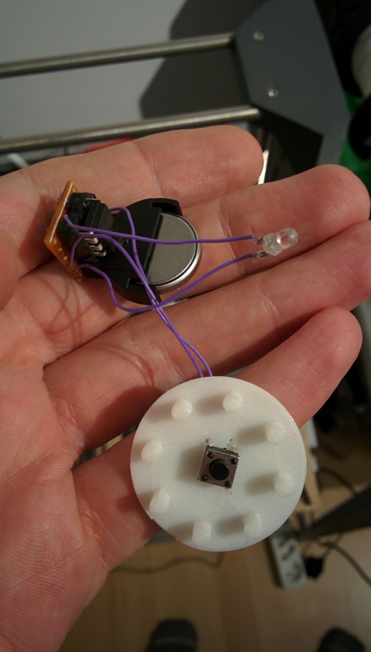
Assembly and first run
Let's begin by the end :)
Concept
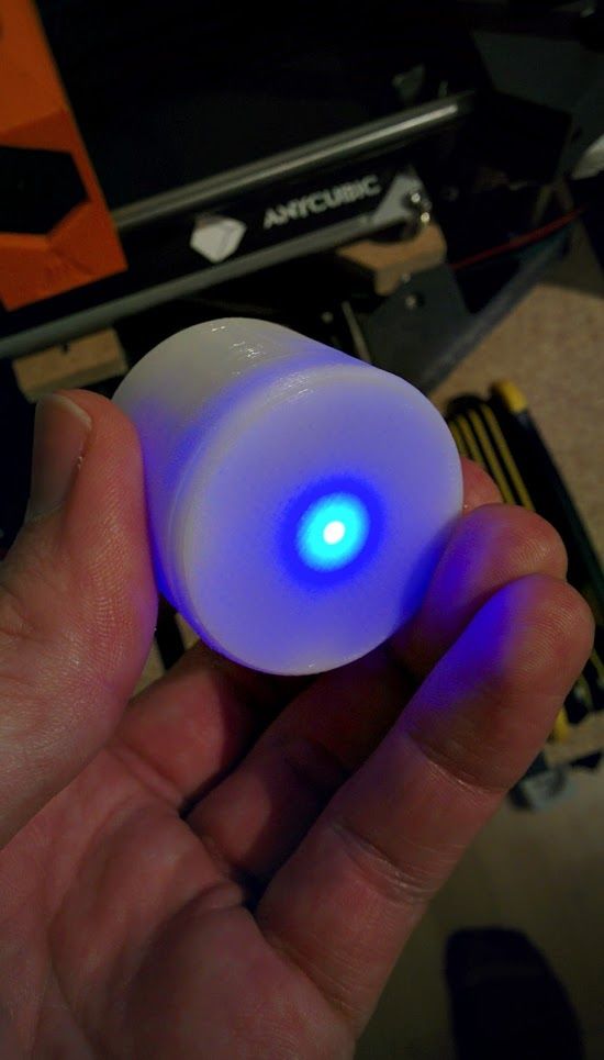
The concept is quite simple and not new. To fall asleep quickly, you have to slow down your breathing. Dodow helps you to do that with a blue pulsing light on the ceiling which will rythm your inspire and expire phases.
I read that the Dodow device begins with 11 breaths per minute and goes down to 6 breaths per minute in a 8 minutes duration.
It worth noticing than the 'expire' time is 50% longer than the 'inspire' time.
I think that the Dodow device can be used during 8 minutes or 20 minutes, and the light power can be adjusted (3 levels). I will not need that in this first version.
First numbers
For 11 breaths per minute:
- breath duration = 60 / 11 = 5.45s
- inspire duration = 5.45 / 2.5 = 2.18s
- expire duration = 5.45 / 2.5 * 1.5 = 3.27s
For 6 breaths per minute:
- breath duration = 60 / 6 = 10s
- inspire duration = 10 / 2.5 = 4s
- expire duration = 10 / 2.5 * 1.5 = 6s
Material
At the end, the device is just a LED pulsing on a define rhythm when a button is pressed. So the list is quite short:
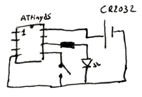
- ATtiny85 (we will use PWM and interrupts, 1 inputs / 1 output)
- Small switch
- Blue LED 3mm crystal clear
- A 10Ω resistor
- CR2032 battery holder + battery
- Wire
- Perfboard
- A case (I will design it)
I used the CR2032 as the discharge curve is almost flat. I will get 3V near the whole life of the battery.
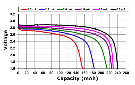
I checked my LEDs, and they even work down to 2.5V.
To use less power as possible, the ATtiny85 will go to deep sleep mode after 8 minutes. I will not use any voltage regulator to not waste any power.
Moreover, the ATtiny will be set on 1MHz clock mode.
Circuit
Very simple...
Power consumption
I measured it with my cheap multimeter :
- Less 0.2µA in deep sleep mode
- Around 1.35mA in use (peek)
So, with an average use of 8 minutes per day, and if I consider that the device uses 1.35mA the whole time when awake, with the CR2032 battery cell (150mAh), we will have:
(150 * 60) / (1.35 * 8 + 1432 * 0.2 * 10-3) ≈ 812
So more than 800 nights !
That's more than enough to test it :)
Source code
LED pulse
I already did some LED pulse on other projects.
Here, I want to follow a specific rhythm.
The basic formula for the LED pulse is :
f(t) = sin(2π * t / d - π/2) * 127 + 127
with 'd' a divider impacting the duration of the pulse period
This formula will allow you to have a beautiful LED pulse, starting off (if t = 0) and using the whole range of power from 0 to 255 (max analog value).
As I don't want to have the same duration for the 'inspire' phase and the 'expire' phase, I will not use the same formula for the two phases:
- the divider 'd' will be computed before each breath to increase the breath time (remember ? 11 breaths per minute to 6 at the end)
Divider 'd' for the different phases
For example, if the duration of the phase is 4s:
f(t) = sin(2 * PI * t / d - PI / 2)
f(4) = sin(2 * PI * 4 / d - PI / 2) = 1
2 * PI * 4 / d - PI / 2 = sin-1(1) = PI / 2
2 * PI * 4 / d = PI
2 * 4 / d = 1
d = 8
GitHub repository
You can find the whole source code on GitHub. I used PlatformIO to build and upload the source code.
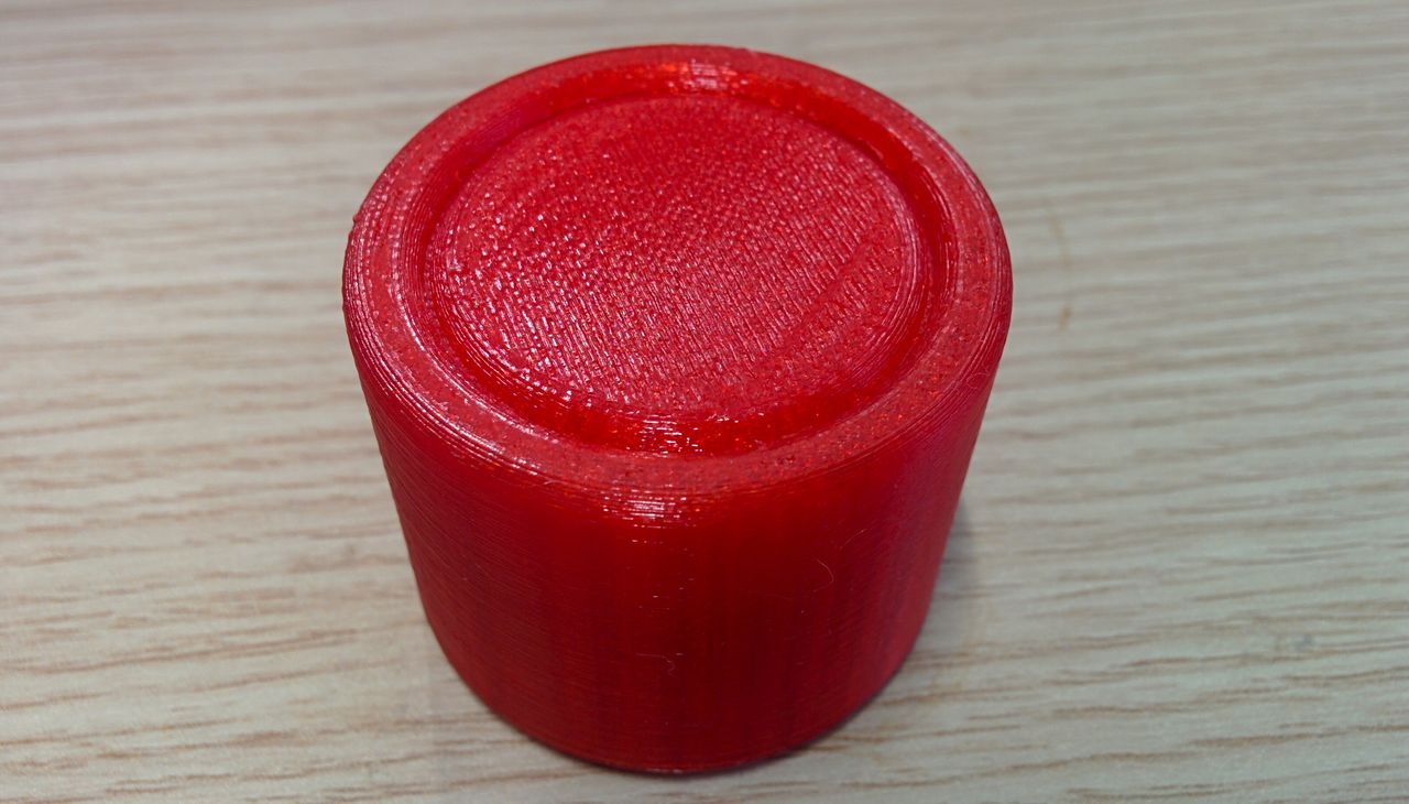
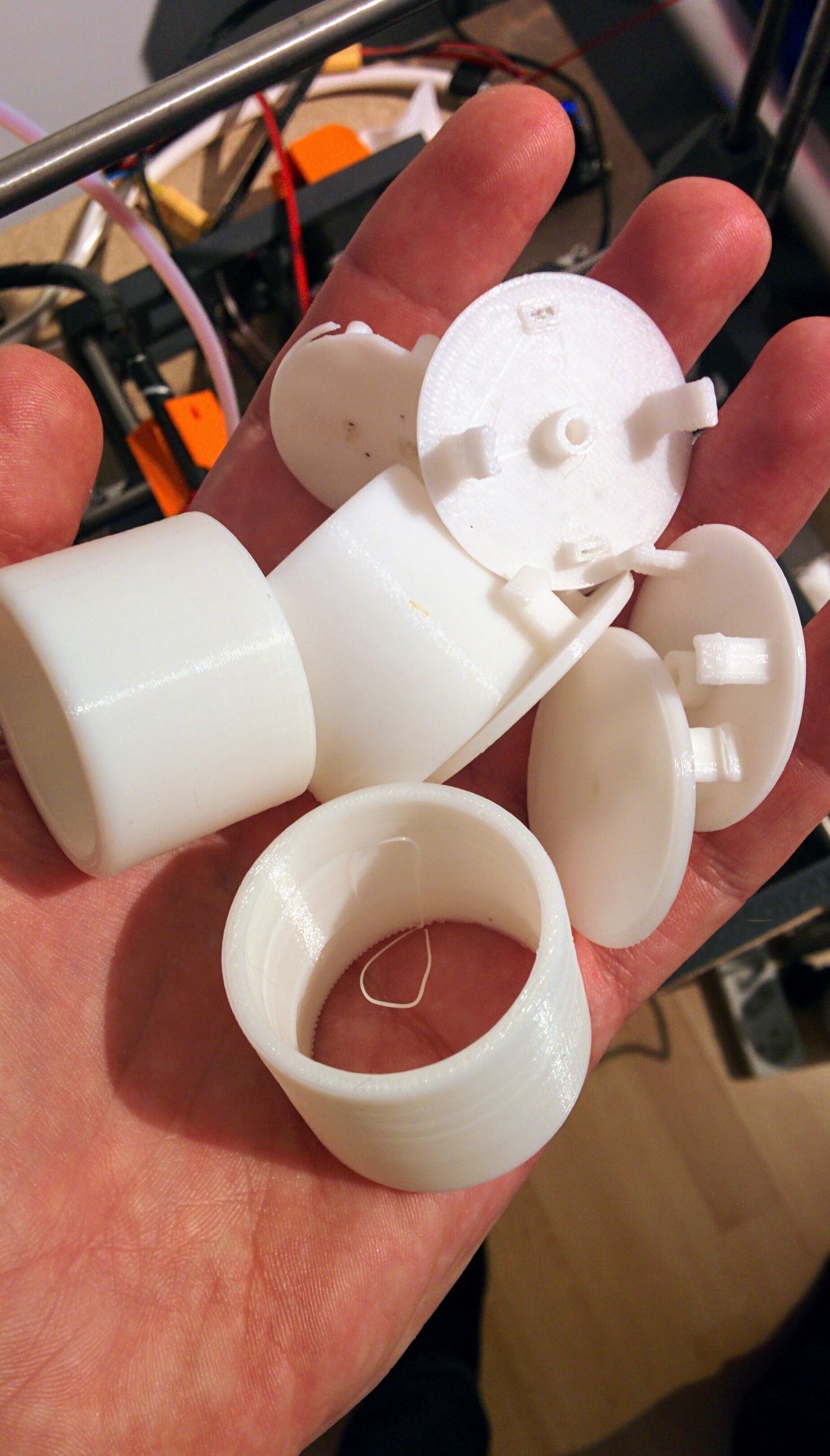
Case
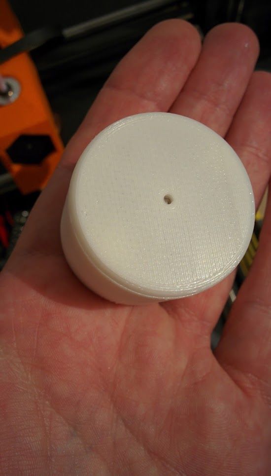
I wanted a smaller format than the Dodow device. I re-used the design of my button to create a cylindric case.
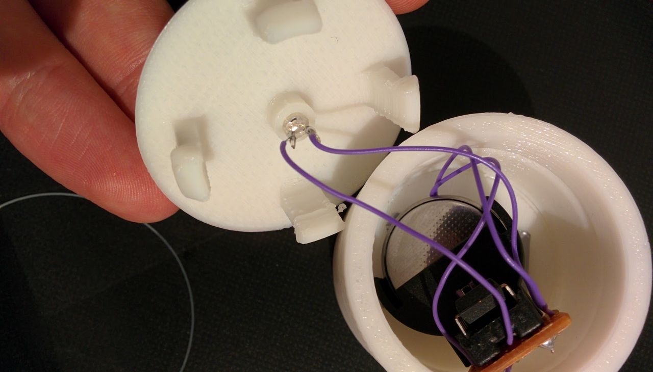
The button to enable / disable the device is located under it, and the LED is at the center of the upper face.
You can download my case on Autodesk website.
At first, I tried to use a white PLA, but one of the pieces always breaks under the pressure.
That's also my fault, as the conception of the pieces doesn't take into account that it is printed on the flat side (and the snap-fit is printed on the Z-axis).
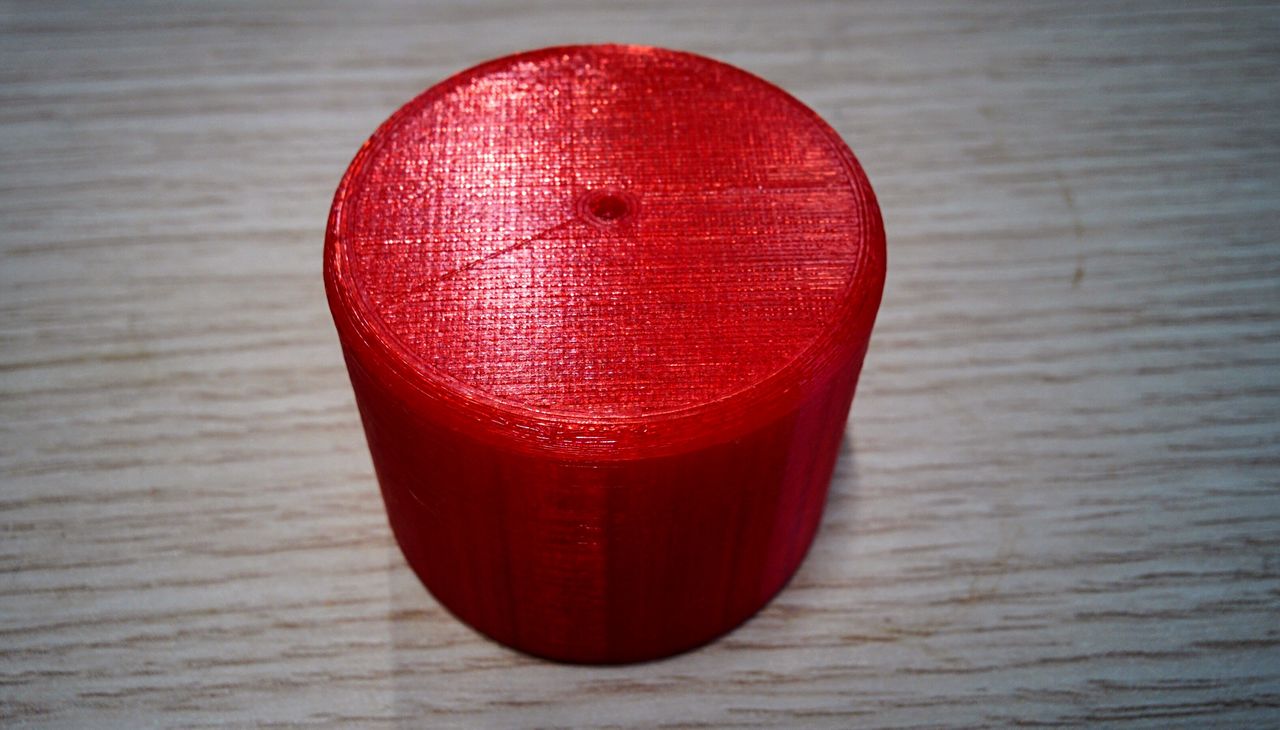
I then used PETG for the top piece, and it worked marvelously !
Sadly, I don't have anything else than red transparent PETG, and I think that the result is less attractive than in white.
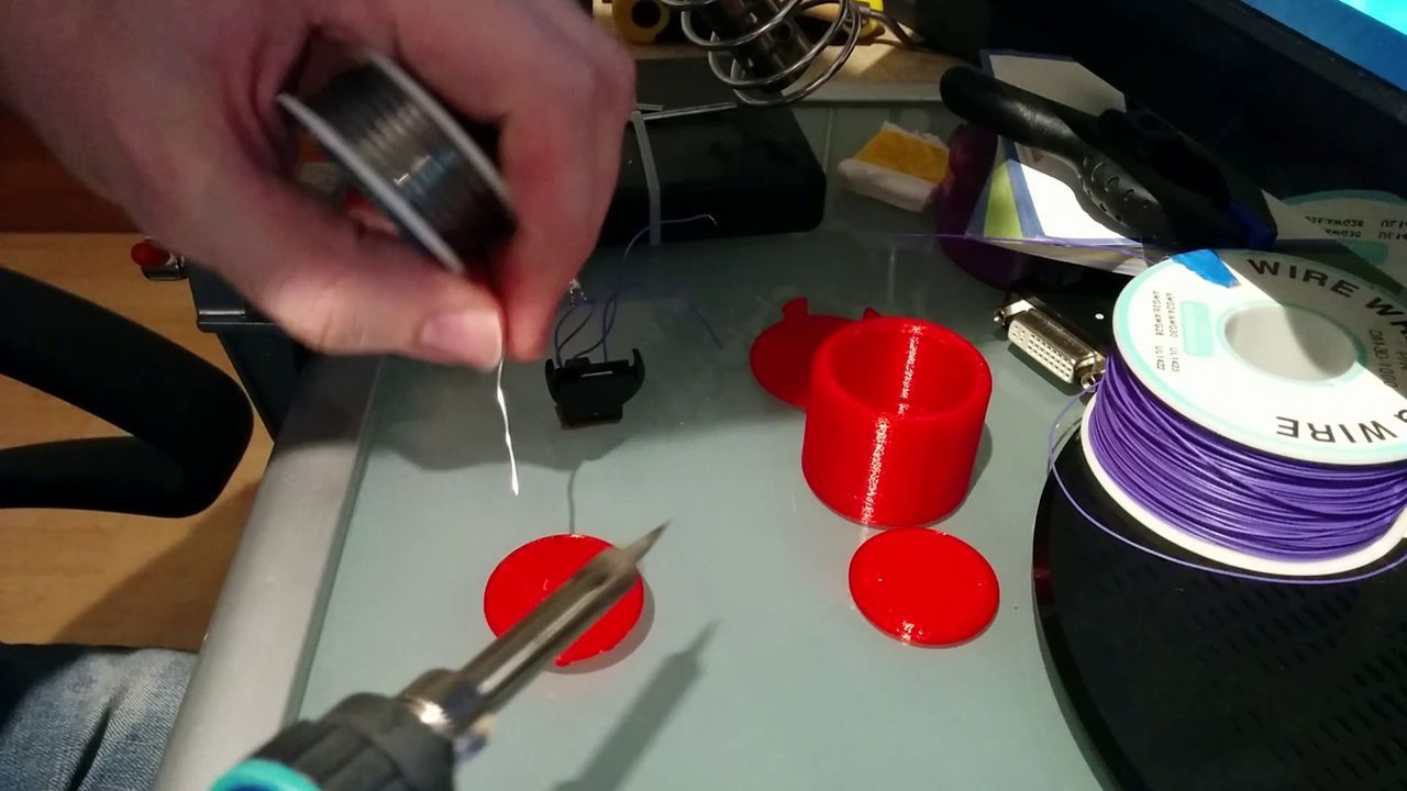
The assembly is quite easy and doesn't require any glue.
You just have to put the switch on one piece, solder it to the wires and connect it to the board.
After that, you just have to snap pieces.
In White (PLA)
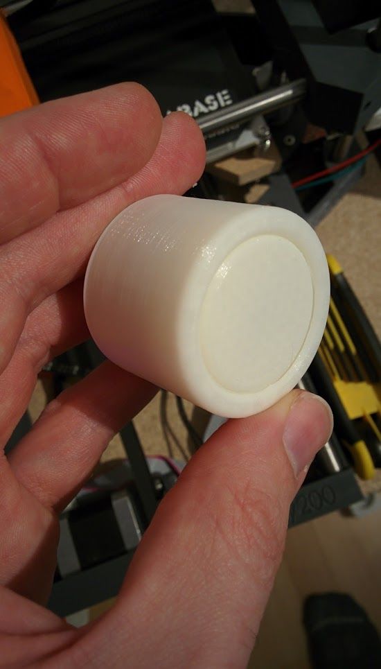
In White (PLA) and Red (PETG)
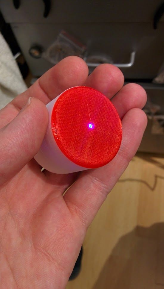
Full red - Full PETG !