Water tank monitor [2]: Components
After reviewing the main parts for my sensors, it's time to decide which electronic components I will use.
![Water tank monitor [2]: Components](https://storage.ghost.io/c/fe/14/fe1439bb-44cb-4fc0-aa30-44bf49d2ab9f/content/images/size/w2000/2016/08/IMG_0487-1-.jpg)
In the first post, I laid the foundations of the two elements for this project: the sensor node and the base station.
In this blog post, I will define the components I will use for each node.
Don't forget that I want to use cheap solutions.
As I previously said, I want to create battery powered nodes, so I will precise power consumption for each component.
Common components
Communication module
For this project, I found two solutions :
- RF 433Mhz, with cheap sensors
- RF 2.4Ghz, with the famous nRF24L01+
My choice is to use the second one, the nRF24L01+, which seems more reliable.
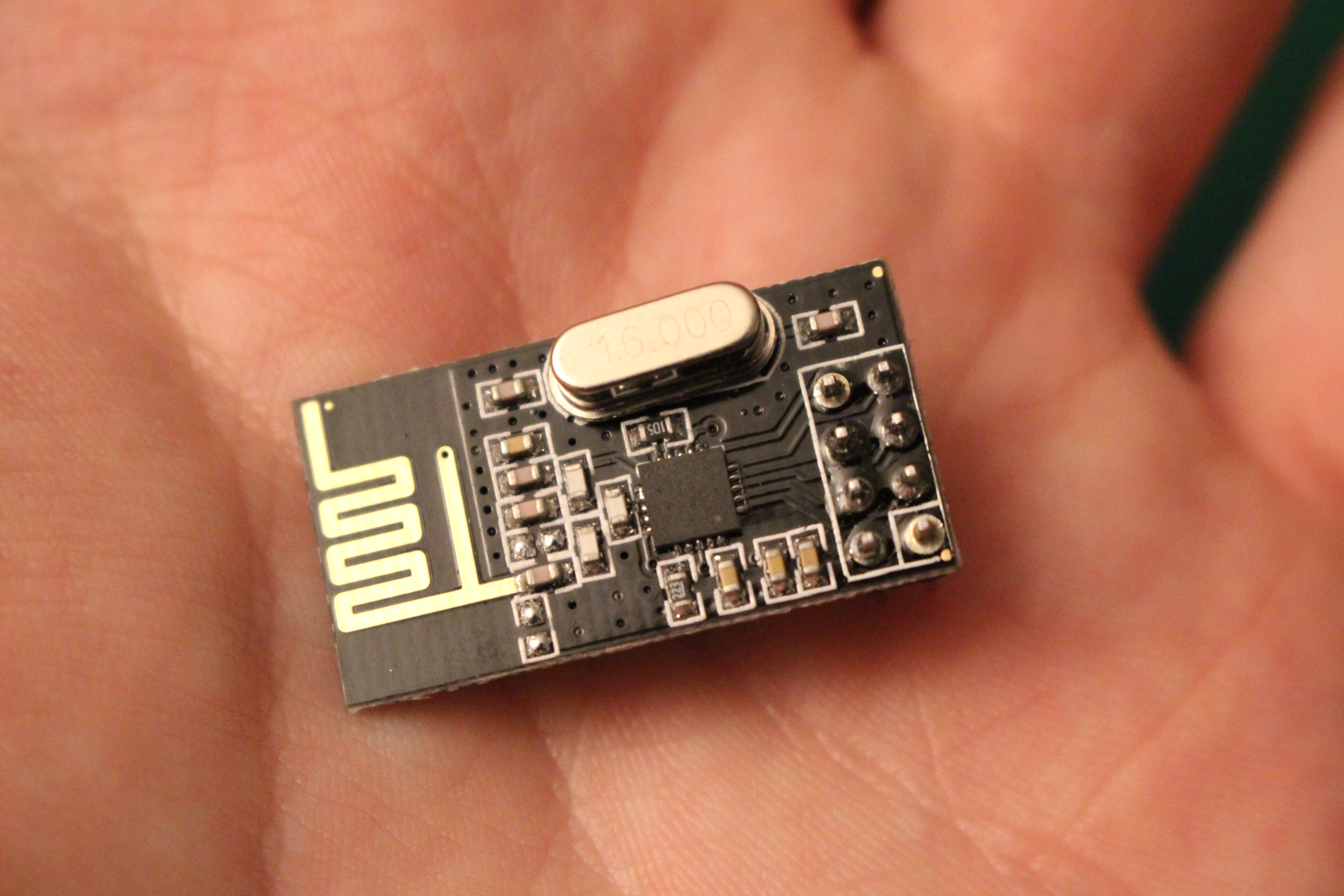
- Power supply: 3.3V, consumption peaks to 30mA (but 5V tolerant input)
- 26µA in standby mode, 900nA in power down mode, consumption peaks to 30mA
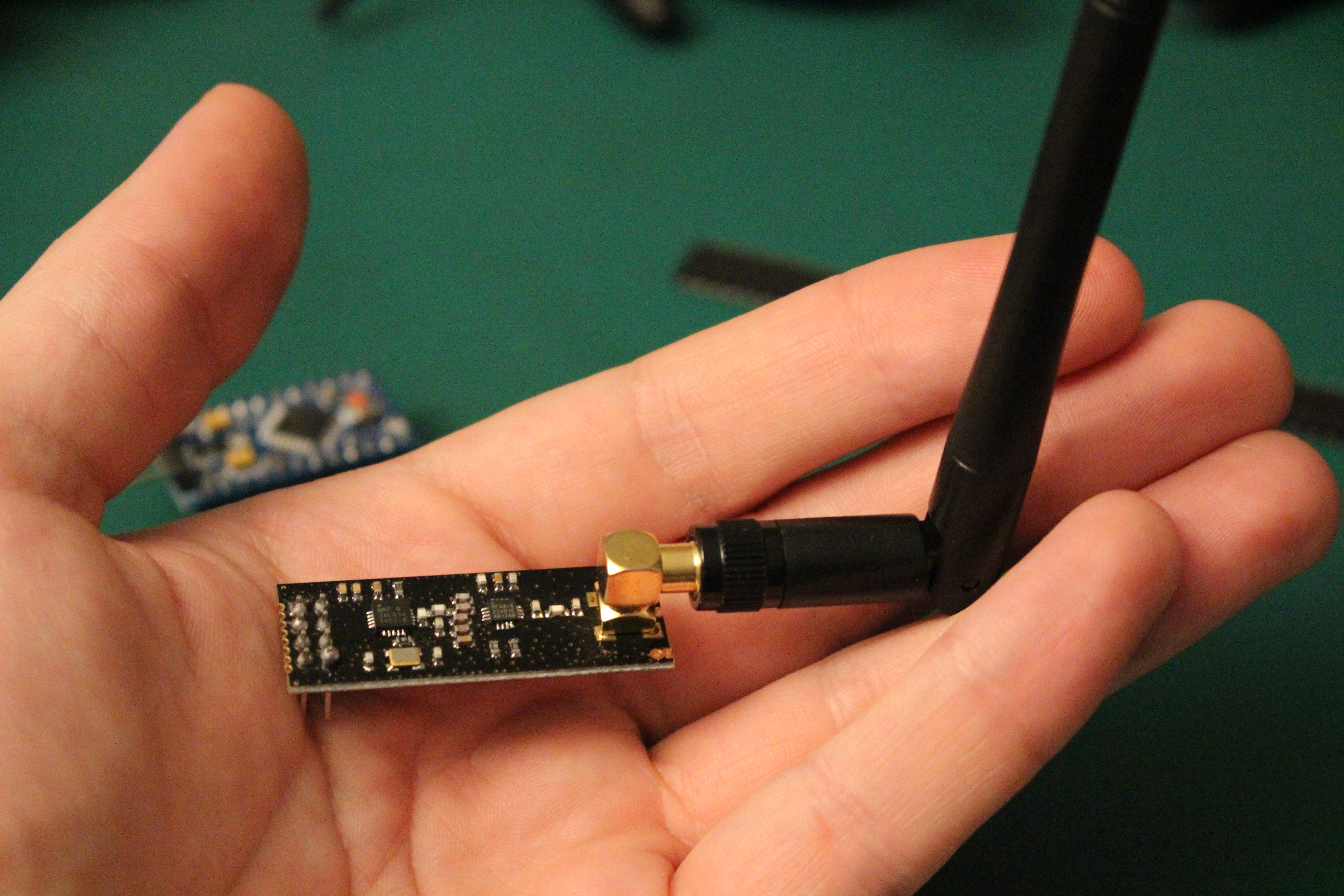
I hope that the range will be sufficient to allow my three devices to talk to each other. If needed, I've also bought the equivalent module with an external antenna.
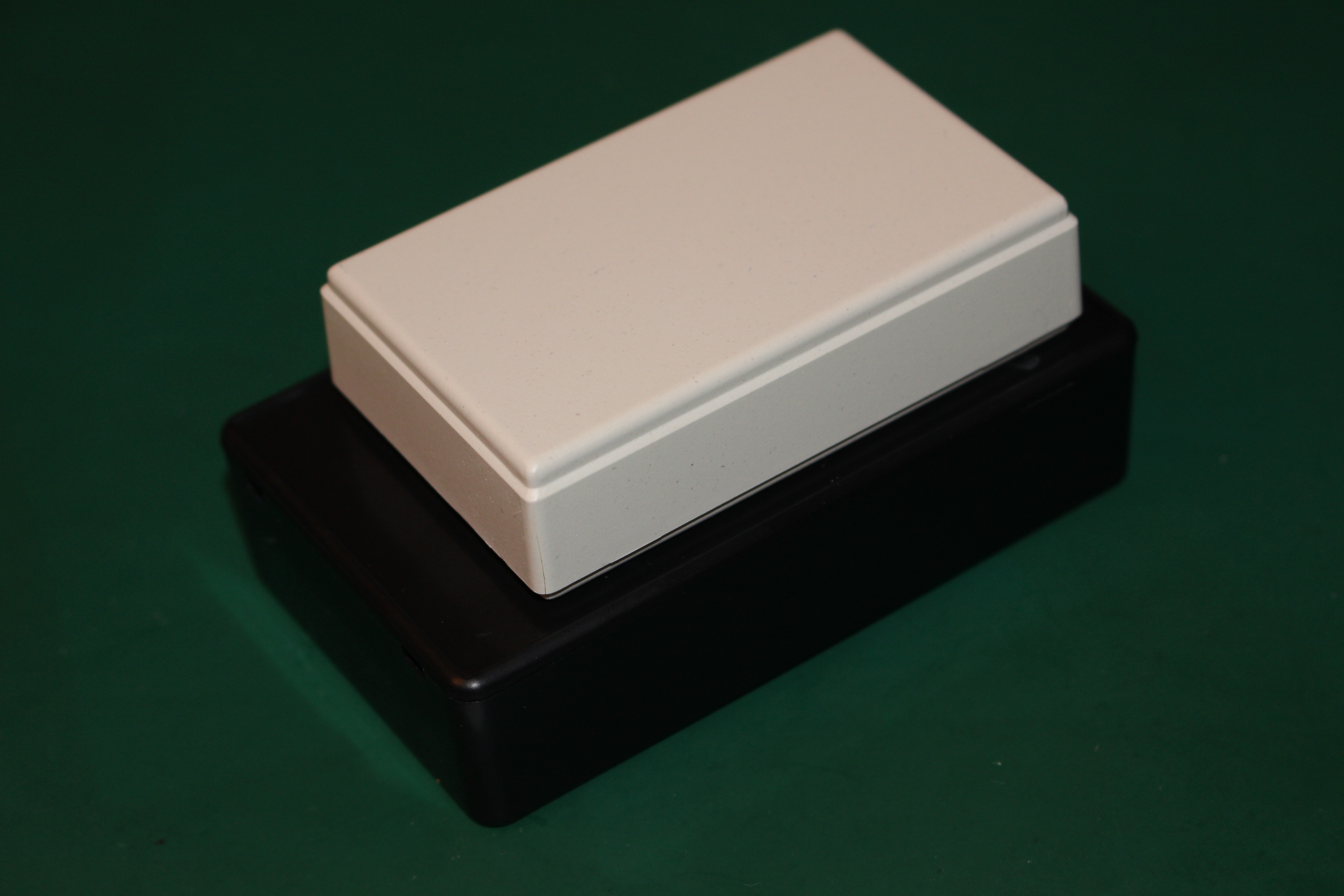
Boxes
I will use some cheap plastic boxes I bought online for less than 1€ a piece.
Base station
As I gave you my opinion on the IoT@Home blog post, the base station should receive RF messages from the sensors, and send the data to the cloud without interpretation (acting as an hardware gateway).
Another component should retrieve the values and display the water tanks level.
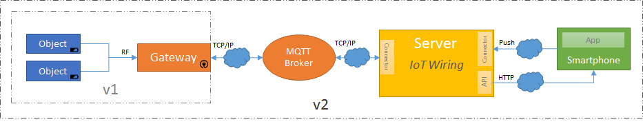
However, in this first version, to reduce cost and complexity, I will break my vision of the "big picture".
Sadly, the chalet is not connected to the internet at all time, and I don't want to pay for an 2G/3G plan (for now).
So, for starters, I will do a simple RF receiver, which will directly interpret and display the data from the sensors.
In a future version, I will use a wifi chip (ESP8266 ?), and a storage unit (microsd card ?) to store the data when the wifi access point is off, and transmit it when on. Or maybe I will bought a GSM module :D
Thereby, the status of each tank will not be displayed on the gateway anymore, but within a mobile app (v2).
Main board
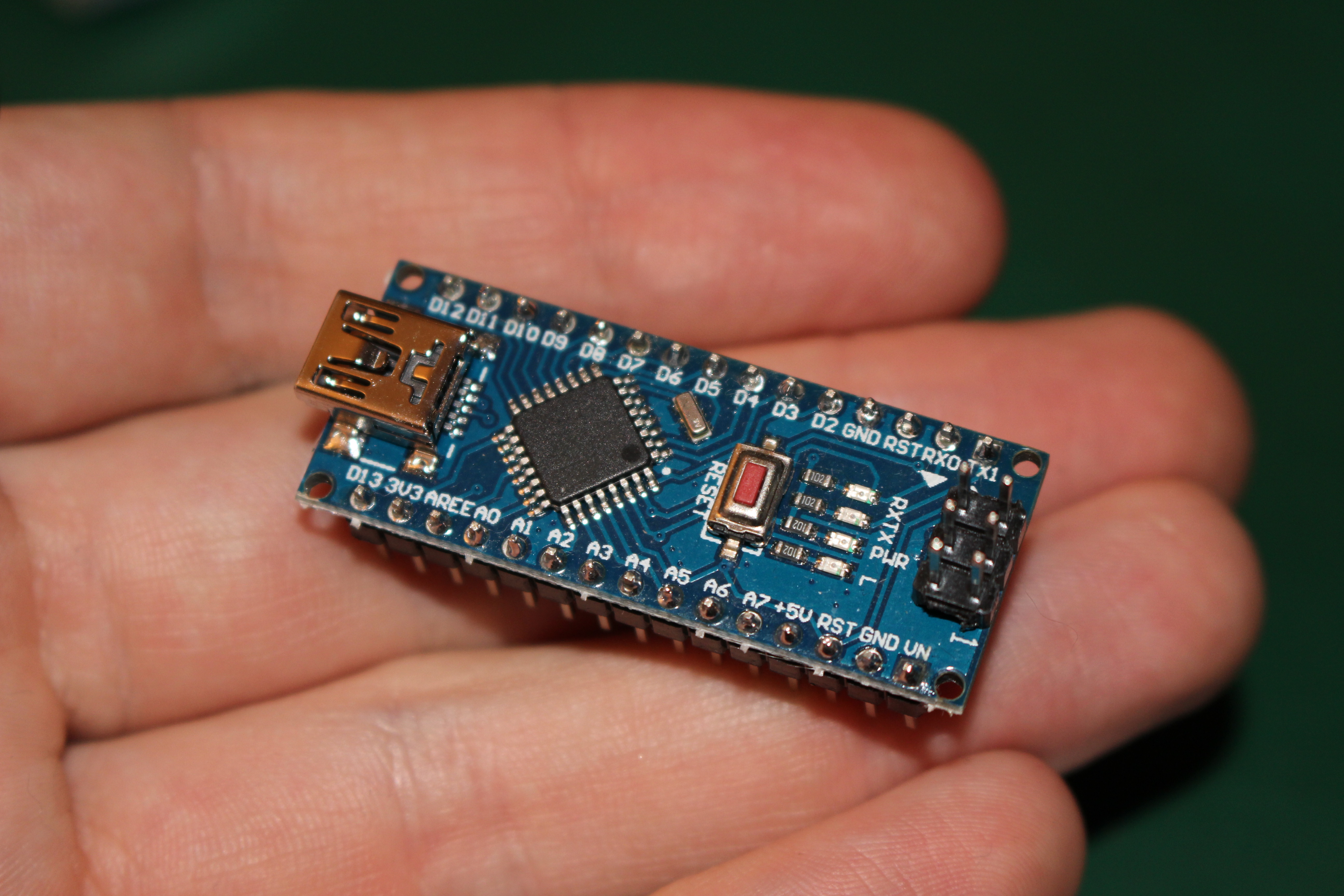
For a compact solution, I will use an Arduino nano, with an external smartphone power supply (USB 5V / 500mA min).
This board is able to provide 5V and 3.3V inputs for other module. However, it is important to note that the Arduino Nano 3.3V regulator has a max current rating of 50mA (source).
As the 3.3V regulator of the Arduino Nano is quite limited, I will maybe use an LDO regulator (I'm thinking HT7333). Even if it is not needed right now for the nRF24L01+ transmitter, it will be mandatory for the ESP8266.
State indicator
For indicating the level of each tank, I will use some RGB LEDs, with common cathode.
I planned to implement these states :
- A color scale, from red to green to indicate the level of the tank
- Flash in blue when a message is received
- Flash in red when the level is very low
- Maybe, if I can detect low battery, flash in white ?
Sensor node
Level sensor
As I said in my previous post, I choose to use an ultrasound sensor to mesure the distance between the sensor and the water.
The common sensor is the HC-SR04.
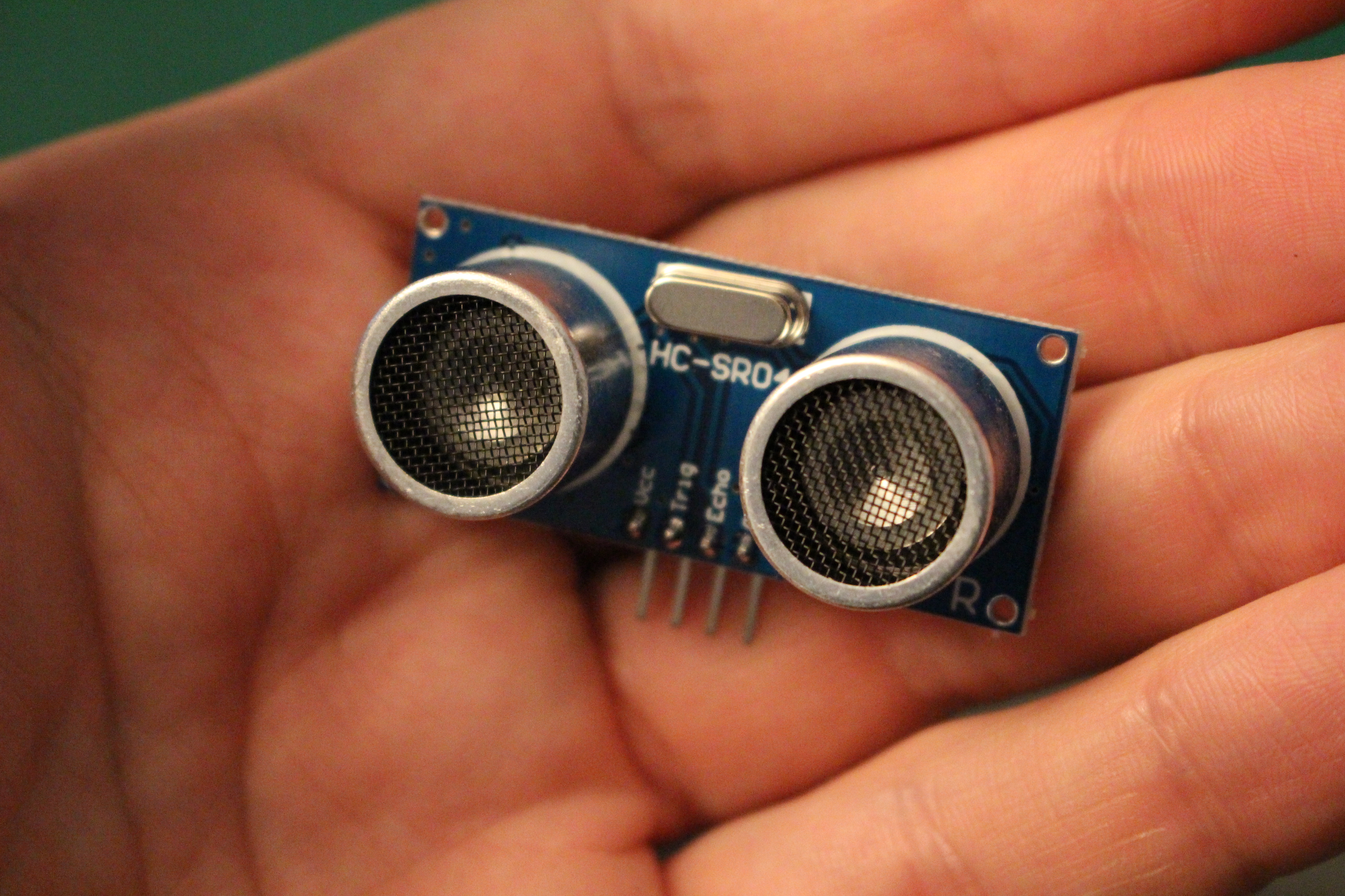
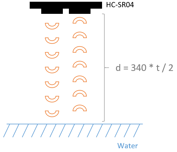
It's easy to use; we just need to send a trigger signal on the "trigger" pin, and mesure the past time until the "echo" pin is high.
This time is the time for the ultrasonic sound to travel from the sensor to the water, and come back to the sensor. Then, we can convert it to centimeters.
- Operating Voltage: min 4.50V, typ. 5.0V, max 5.5V
- Quiescent Current: min 1.5mA, typ. 2mA, max 2.5 mA
- Working Current: min 10mA, typ. 15mA, max 20mA
One problem though, this sensor is power hungry, even when no measurement is done.
We will need to power it off / on when needed. I should use a mosfet, but I don't have one yet. I will use an NPN transistor instead (an 2N2222).
Batteries
As I said in the first post, each tank is closed, so the sensors have to be powered for at least one year without changing the batteries.
I will use Alkaline AAA or AA batteries:
- I don't want have to recharge batteries once a year, so no rechargeable batteries;
- Alkaline batteries have a great capacity;
- Alkaline batteries are affordable.
I will not use 9V batteries because they are quite expensive, and have a small capacity compared to AA or AAA batteries. Moreover, I do not need 9V to power the sensor node.
I advise you to compare the capacity of each type of batteries through the dedicated Wikipedia page.
Main board
So, this choice is not easy:
- Has to be compact
- Low consumption
- Two power levels to manage: 3V3 and 5V
- Powered by 3 AAA batteries (to be close to 3V3 and 5V without using to much space)
I will use an Arduino Pro Mini, which doesn't consume a lot of power in deep sleep, with some hardware modifications (we will talk about that later).
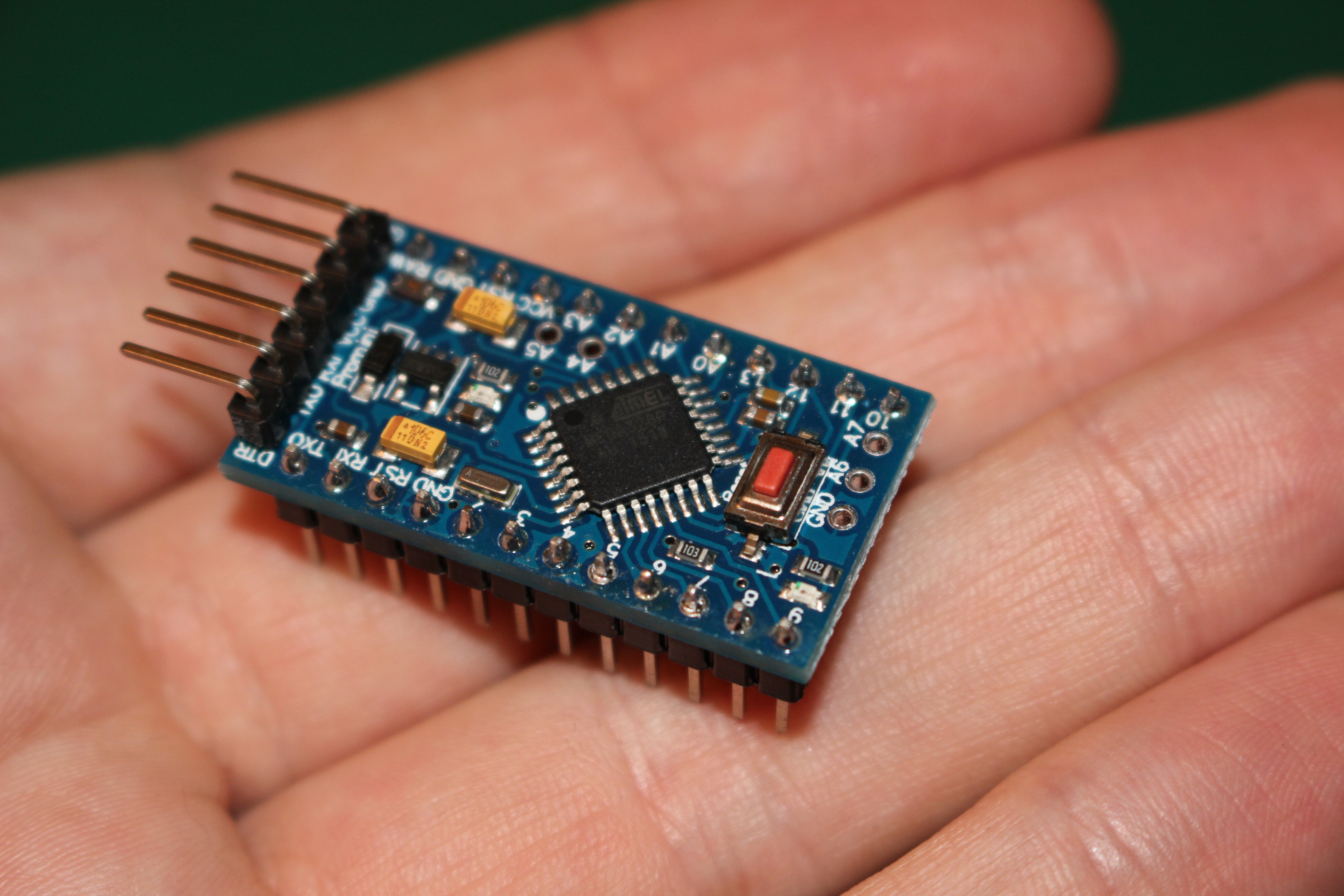
The Arduino Pro Mini comes in two packages :
- 3V3 @ 8Mhz
- 5V @ 16Mhz
It could be easier to use an 5V Pro Mini, as I have to manage 3V3 and 5V modules.
However, I didn't find any efficient (and cheap) step-up regulator, to output 5V with less than 4 batteries.
Moreover, even if I use 4 batteries (1.5V * 4 = 6V) and a step-down, the power of each battery will decrease with time, and will quickly go below the required 5V.
For these reasons, I will use the Arduino Pro Mini 3.3V.
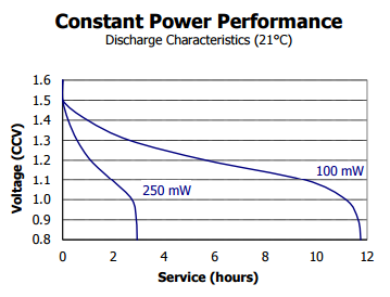
Example with an AAA Energizer battery
Step up converter
As the main board run on 3.3V, and the sensor needs 5V, I need to use a step up converter.
As I said before, I didn't find any cheap and efficient step up converter.
So I bought a small card, based on the MT3608. With this card, the output voltage can be selected thanks to the potentiometer.
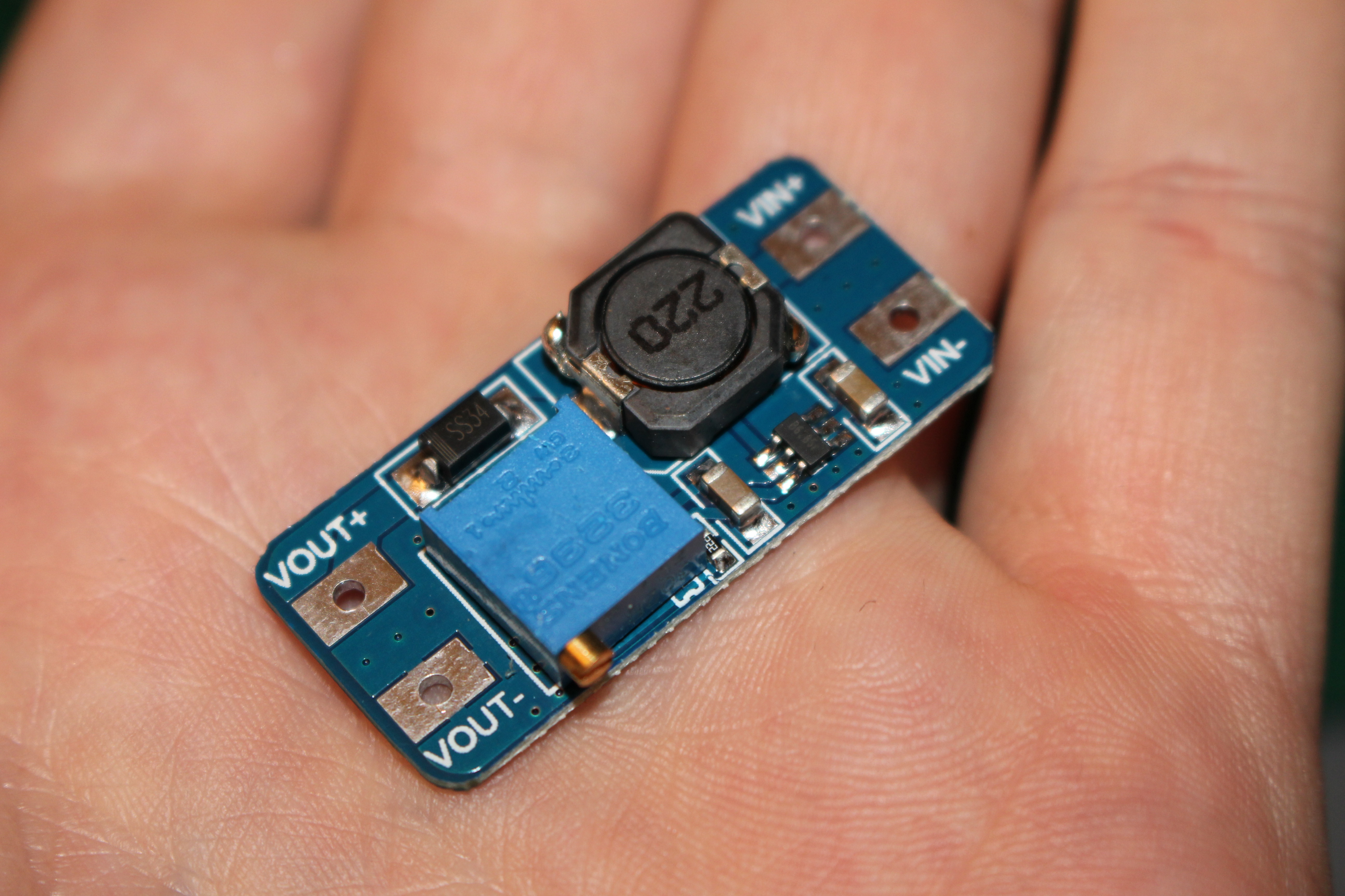
Remark: I bought 5 of these, and at first, I thought that they were damaged: you have to turn the screw of the potentiometer at least 15 times to the left to see the voltage increase.
Sum-up
Base station
- Arduino Nano (5V / USB)
- Note : The Arduino Nano 3.3V regulator has a max current rating of 50mA (source)
- RF24 transmitter (nRF24L01+)
- Power supply 3.3V, consumption peaks to 30mA (but 5V tolerant input)
- Step down converter (3.3V) to supply the nRF24L01+ / ESP8266 : HT7333 (4.3V to 3.3V, up to 250mA current, 4-8µA when no load)
- Powered by an USB wall adapter (5V / 500mA min)
- 2 RGB LEDs and some resistors
Sensor nodes
- Arduino Mini Pro 3.3V @ 8MHz
- Ultrasonic sensor (HC-SR04)
- Operating Voltage: min 4.50V, typ. 5.0V, max 5.5V
- Quiescent Current: min 1.5mA, typ. 2mA, max 2.5 mA
- Working Current: min 10mA, typ. 15mA, max 20mA
- RF24 transmitter (nRF24L01+)
- Power supply: 3.3V, consumption peaks to 30mA (but 5V tolerant input)
- 26µA in standby mode, 900nA in power down mode
- Powered by AAA batteries (3x1.5V = 4.5V)
- Step up converter (5V) for the HC-SR04 (MT3608 as I didn't find cheaper / better)
- Level shifter 3.3V / 5V for interfacing the sensor and the Arduino
- Mosfet to power on / off the step-up converter / HC-SR04, or an NPN if I don't get my mosfets in time.
Next step
Now, I think that I have all the components to build the first version of the node sensor and the base station. Let's try it :)