WiFi Gateway
I quickly built a simple WiFi gateway around a bare-bone ESP8266 to be able to test a sensor module.
Two years ago, I had some difficulties with a 3G node, receiving and transmitting data from another electronic card on an RS232 port.
To be able to continue to follow the data generated by the electronic card, I created a small WiFi node.
I think it's time to share it!
Characteristics
Some characteristics of the gateway:
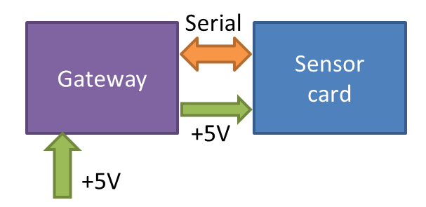
- Every message received on the RX software serial port is transmitted to an HTTP endpoint (POST method). An acknowledge character is then sent on the TX software serial port.
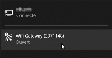
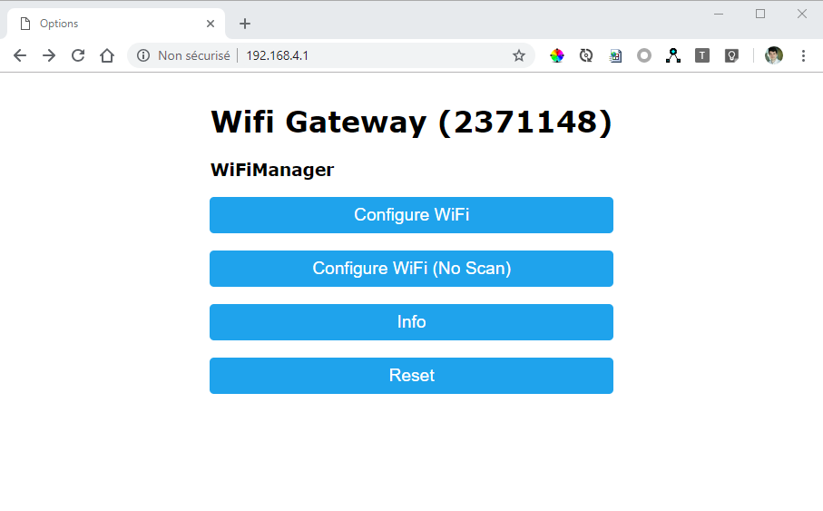
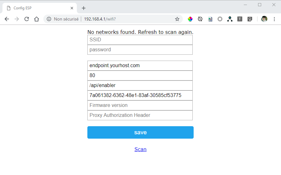
- The WiFi SSID and password can be configured by pressing on the pairing button. The gateway will act as an access point with a webportal to set the configuration
- The gateway has an internal clock synced with an NTP server
- The gateway is configured to send a keep-alive signal every 24h
- The firmware can be upgraded OTA, using ESP8266HTTPUpdate
- It has a FIFO of 20 messages
Material
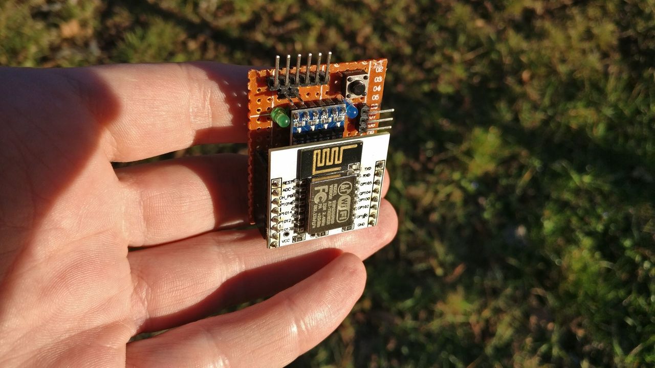
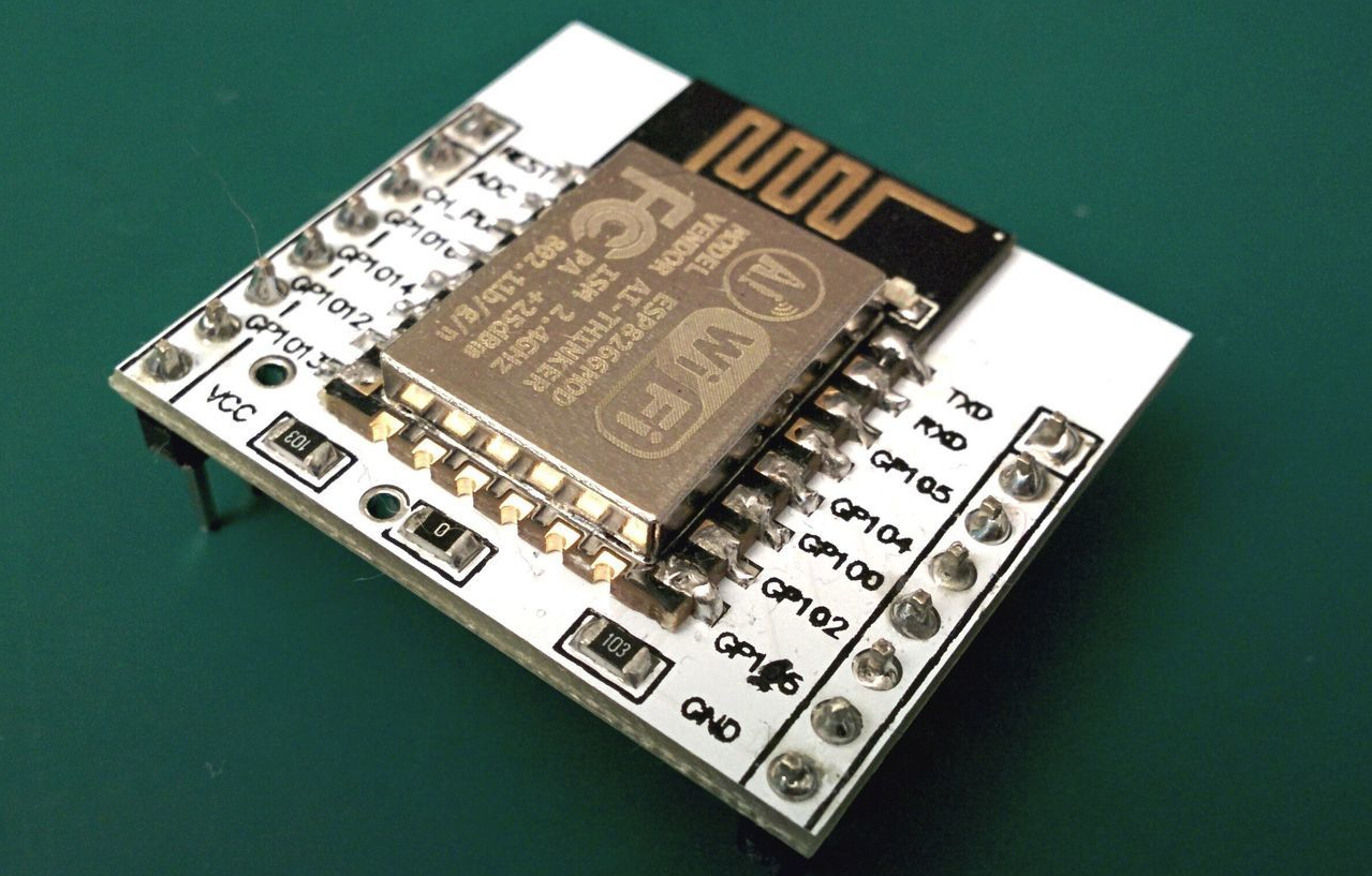
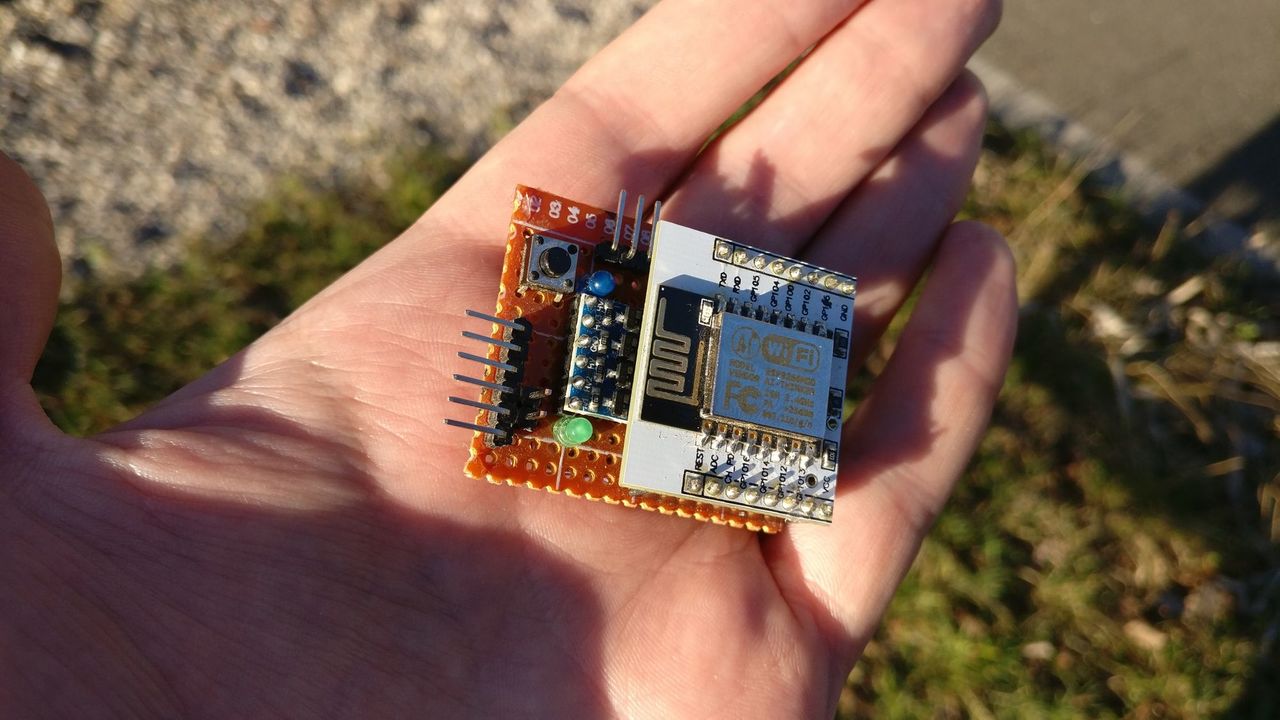
I used an ESP8266 to build my node, with an breadboard adapter.
At the time, I didn't know that the Wemos D1 mini existed. I also tested it afterwards and it works fine with it!
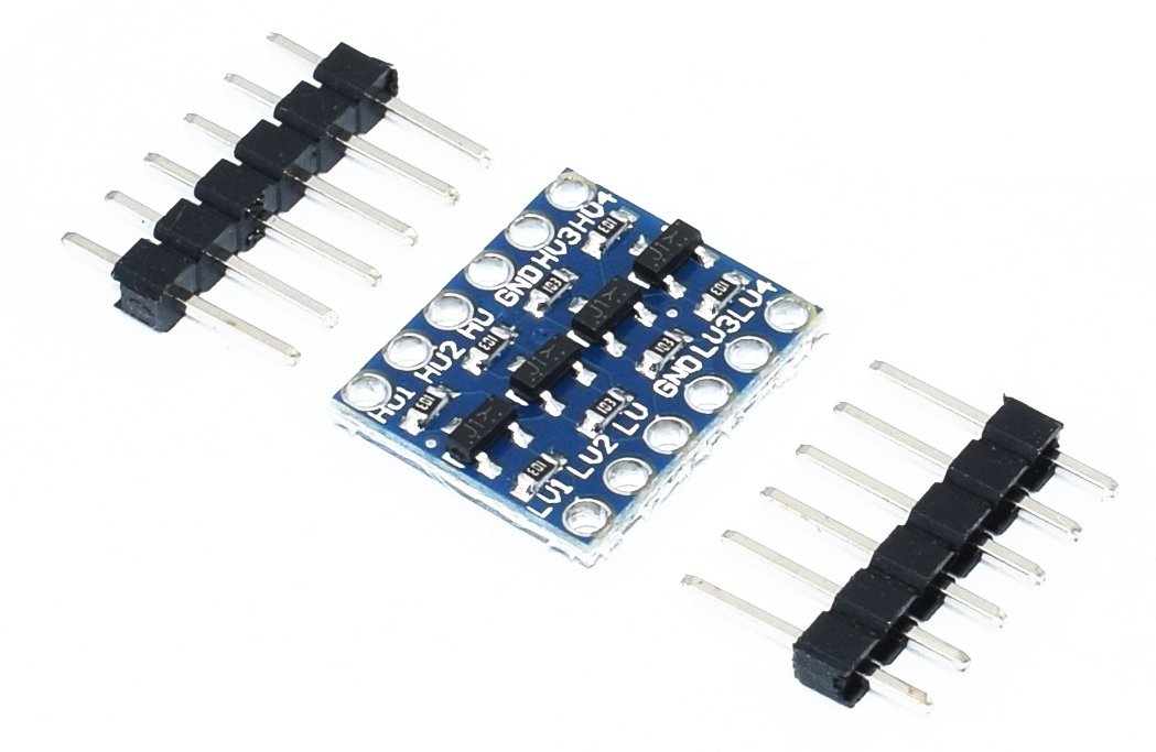
The other electronic card is powered in 5V, so I had to use a level converter to connect to the serial port of the other electronic card.
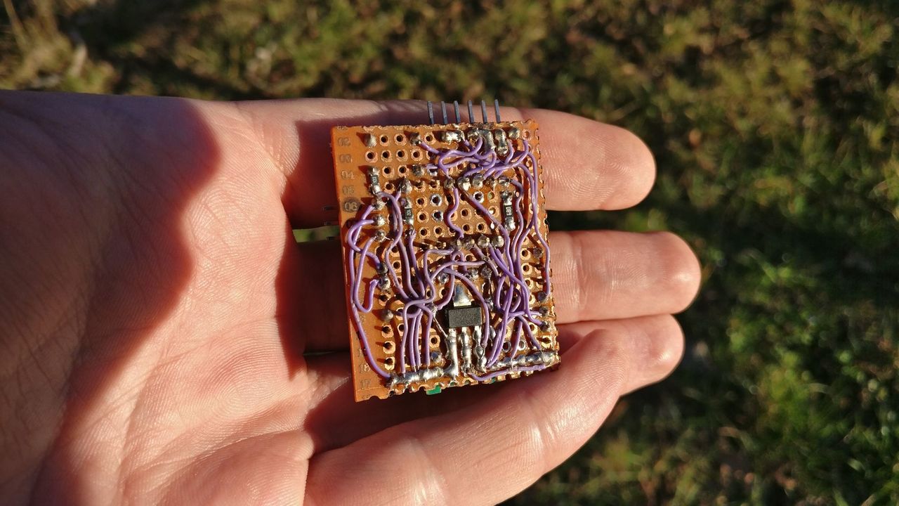
Circuit board
As I use the ESP8266 adapter board, I removed the flash and reset buttons. To flash the ESP, I unplug the adapter board and put it on another breadboard with all the components required to flash the board.
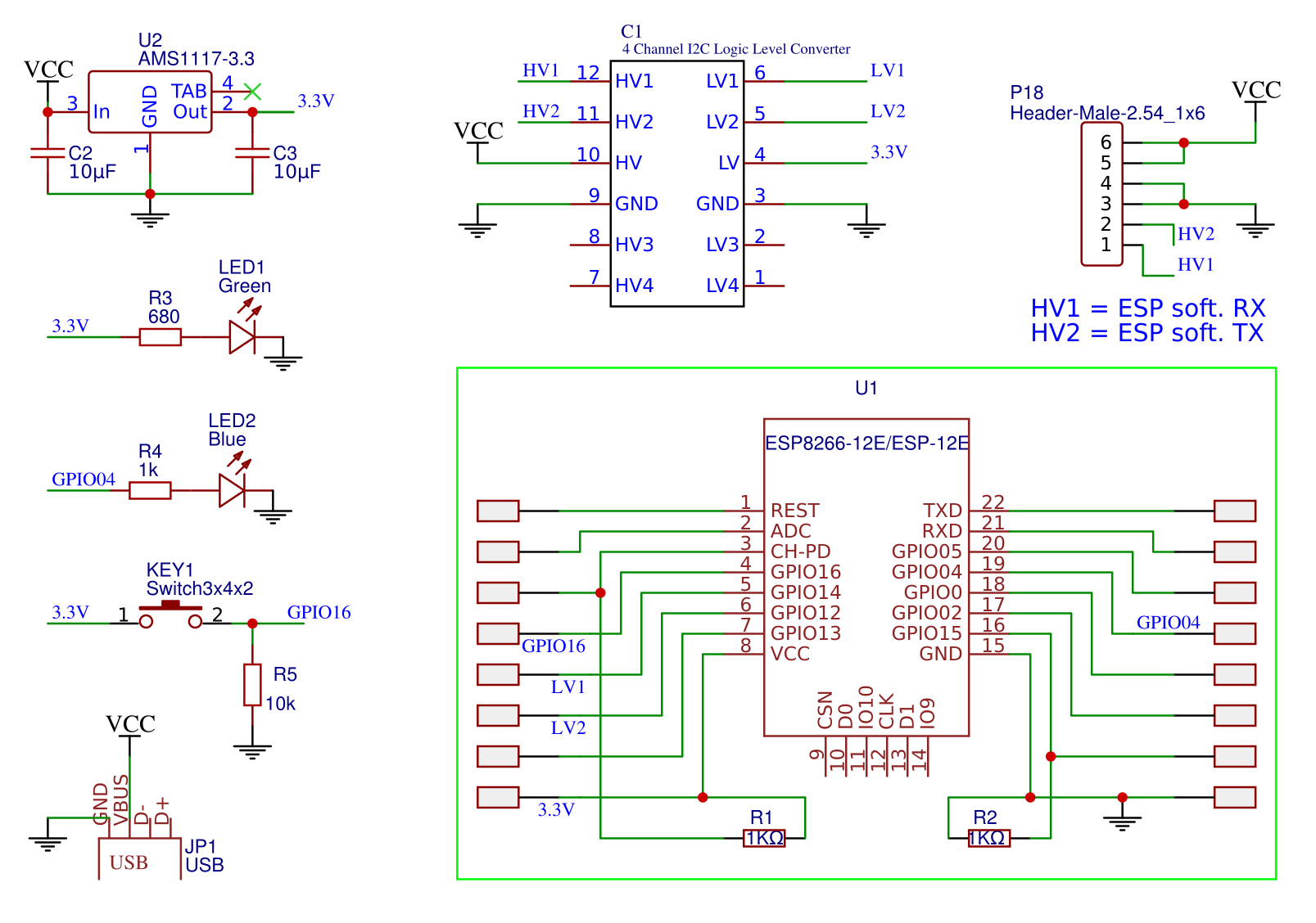
- ESP Power supply: AMS1117 3.3V + capacitors
- Power LED: Green LED (and resistor - 680Ω) between 3.3V and GND
- Pull-down on GPIO15 (requested by the module - done by the adapter board)
- Reset button: Pull-up on the RESET pin with a switch to set it HIGH - removed on 2nd iteration
- Flash button: Pull-up on the GPIO0 with a switch to set it LOW - removed on 2nd iteration
- Pairing mode button: Pull-down (10kΩ) on GPIO16 with a switch to set it HIGH
- Pairing status / message TX LED: Blue LED on GPIO4 (with a limiting resistor - 1kΩ)
- Enable the ESP: Pull-up on CH_PD (done by the adapter board)
- Level converter 3.3V to 5V on serial IO to exchange data with the sensor board
- The GPIO 12 and 13 are used as serial RX/TX to exchange data with the sensor board
- RX / TX pins are linked to a pin header and used to program the ESP.
Source code
If you read my article on the IoT Tardis audio player, you will see that the source code is quite similar.
I removed the source code parts specific to my system.
Without any rework, the gateway will send the payload received on the serial port to the endpoint of your choice. It also adds three headers to track the signals sent by your gateways:
- X-fwv: firmware version
- X-gwid: gateway ID
- X-WiFi-Gateway: always 'true'
The configuration can be done with the build flags located in the platformio.ini file.
build_flags =
  -D VERSION_CODE=1
  -D DEFAULT_SERVER_HOST=\"endpoint.yourhost.com\"
  -D DEFAULT_SERVER_PORT=80
  -D DEFAULT_SERVER_URL=\"/api/enabler\"
  -D DEFAULT_GATEWAY_ID=\"7a061382-6362-48e1-83af-30585cf53775\"
  -D HTTP_UPDATE_HOST=\"endpoint.yourhost.com\"
  -D HTTP_UPDATE_PORT=80
  -D HTTP_UPDATE_URL=\"/api/firmware\"
Some of those options can be overridden during the configuration of the Gateway through a web portal.
You can get the source code of the WiFi Gateway on GitHub.
Board
Next iteration
This gateway was a quick and dirty way to let me continue to work on the main project.
A WiFi gateway have some drawbacks, the main one being dependent of a WiFi network, and, in my case, a non reliable network.
The next iteration will be a 2G gateway, made of cheap (Chinese) components.